Greetings,
I'm trying to repair a Integra RDC-7 and the issue that I have is a lot of noise in the main RL outputs when the sample frequency is 48Khz. In 96Khz the sound is ok.
So after some analysis I measured the PLL output frequency and it is 18.432Mhz ( 96Khz x 24bit x 8oversampling), but when the sample frequency changes to 48Khz the PLL output is still 18.432Mhz.
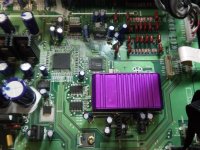
Does someone know where to get a new PLL? (it's the purple thing in the picture and the reference in the schematic is CC1536E) And should I try to open the case?
I also marked the clock signals in the schematic(Blue-sample frequency, Green-PLL output , Red- Bit clock and word clock to DAC).
Thanks
I'm trying to repair a Integra RDC-7 and the issue that I have is a lot of noise in the main RL outputs when the sample frequency is 48Khz. In 96Khz the sound is ok.
So after some analysis I measured the PLL output frequency and it is 18.432Mhz ( 96Khz x 24bit x 8oversampling), but when the sample frequency changes to 48Khz the PLL output is still 18.432Mhz.
Does someone know where to get a new PLL? (it's the purple thing in the picture and the reference in the schematic is CC1536E) And should I try to open the case?
I also marked the clock signals in the schematic(Blue-sample frequency, Green-PLL output , Red- Bit clock and word clock to DAC).
Thanks
Attachments

The way that the master clock generator works is that the FPGA (Q8704) would tell, based on the incoming sampling frequency it sees, the master clock module (or PLL module as you marked in the schematic) what scale setup the counters in the module should be working at by three control lines: FS0, FS1, and FS2. So when the MCLK output does not change its frequency upon switching to a different sampling frequency as you experienced, first thing I would do is to see if there is anything changes accordingly on the three control lines.
Last edited:
The way that the master clock generator works is that the FPGA (Q8704) would tell, based on the incoming sampling frequency it sees, the master clock module (or PLL module as you marked in the schematic) what scale setup the counters in the module should be working at by three control lines: FS0, FS1, and FS2. So when the MCLK output does not change its frequency upon switching to a different sampling frequency as you experienced, first thing I would do is to see if there is anything changes accordingly on the three control lines.
Thank you so much,
I noticed those 3 lines, but didn´t know what they were for, and yes they are always low.
I tought the master clock module would detect the sampling frequency and set the counters. So it seems the problem comes from de FPGA or the main microcontroler in another board, I already replaced the 74hct7007.
Last edited:
If need to prove the master clock generator functionality you probably could lift the 74hct7007, and manually force some combinations of F[0:2] and see if you can get it to work with 48KHz properly.
If need to prove the master clock generator functionality you probably could lift the 74hct7007, and manually force some combinations of F[0:2] and see if you can get it to work with 48KHz properly.
Thanks again, I did that and the clock is working fine.
- Status
- Not open for further replies.