I just received a cheap (90€) "PA" amp that is supposed to have "480 Watt max achievement at 4 ohms (2 x 160 Watt at 8ohm)" I bought it for 15€ because it was broken, just to see what's inside.
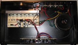
This is what I found:
- A lightweight 2 units 19" rackmount enclosure.
- 2*26V torroidal transformer, weight between 1.2kg and 1.5kg. So I estimate it at no more than 120VA.
- 4000µF of power supply capacitors 😱
- Very loud fan that is always on full speed.
- a tiny heatsink.
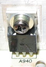
- 8 blown mosfet's and 2 burnt resistors. Mosfet's read A940 on them, but I can't find any mosfet that matches this part number.
- A rare level of build quality.
As you can see, a "real" performer. 😀
I traced the schematic just to check if this amplifier self-destructs by design. Anyone has some thoughts on the performance of this circuit?
edit: non mosfet transistors are 2SC1815 (npn) and 2SA1015 (pnp)
This is what I found:
- A lightweight 2 units 19" rackmount enclosure.
- 2*26V torroidal transformer, weight between 1.2kg and 1.5kg. So I estimate it at no more than 120VA.
- 4000µF of power supply capacitors 😱
- Very loud fan that is always on full speed.
- a tiny heatsink.
- 8 blown mosfet's and 2 burnt resistors. Mosfet's read A940 on them, but I can't find any mosfet that matches this part number.
- A rare level of build quality.
As you can see, a "real" performer. 😀
I traced the schematic just to check if this amplifier self-destructs by design. Anyone has some thoughts on the performance of this circuit?
edit: non mosfet transistors are 2SC1815 (npn) and 2SA1015 (pnp)
Attachments
Last edited:
Datasheet for 2SA940. Btw, he seems cracked on that picture! 😕
http://www.datasheetcatalog.org/datasheet/mospec/2SA940.pdf
Edit: I think this would be the proper circuit?
http://www.datasheetcatalog.org/datasheet/mospec/2SA940.pdf
Edit: I think this would be the proper circuit?
An externally hosted image should be here but it was not working when we last tested it.
Last edited:
Pretty rubbish circuit with resistive load for VAS. I think you may have the 0.22 ohm resistors the wrong way round - they should be in the sources. Maybe this is what caused failure.
I just received a cheap (90€) "PA" amp that is supposed to have "480 Watt max achievement at 4 ohms (2 x 160 Watt at 8ohm)"
If it is on 35V rails then peak power is 35^2 / 8 = 153W, so RMS power is 76.5W, allowing for loss in the resistors and mosfets you'd probably get 70wpc from it.
Of course my maths is a bit rusty - correct me if I'm wrong!
ooops, propering the proper 😀
An externally hosted image should be here but it was not working when we last tested it.
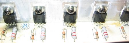
I checked and double checked the circuits around Q1, Q6 and Q7. They are as indicated on my schematic. All 0.22 resistors are on pin 3 of each "mosfet".
All 8 "mosfets" have the same markings: A940. I'm confused as marketing blurb said "modern MOSFET technology". As some other members mentioned, I can only find the PNP transistor with this name. All 8 are broken, so it's impossible to say if they measure as a fet, pnp or npn.
I found some people with the same broken amplifier and they also report that all "mosfets" have the same A940 marking.
Attachments
Well, if my eyes are still good, there is a Fairchild logo on those transistors. Fairchild doesn't manufacture 2SA940 but they do under a different name, KSA940 which is again BJT PNP. Maybe they are fakes from China, dunno. 😕
http://www.fairchildsemi.com/ds/KS%2FKSA940.pdf
http://www.fairchildsemi.com/ds/KS%2FKSA940.pdf
It looks very much like the inside of cheap amp I bought off ebay.
I was shocked at the minmal heatsink and transformer for the wattage specified for the amp.
The amp worked but definitely did not give the wattage advertised.
I was shocked at the minmal heatsink and transformer for the wattage specified for the amp.
The amp worked but definitely did not give the wattage advertised.
I'm curious though, how does 2x16V transformer provide enough voltage for +/- 35V rails using a simple rectifier bridge ?
OP says 2x26v... 26 x 1.414 = 36.7vdc
Well, the "mosfets" look exactly like the KSA940, a PNP transistor. I wonder why they would use an all PNP output stage. Looks like a design from the late 1950's. Also there is no temperature compensation at all, so it is possible that these amps self-destruct by thermal runaway.
I'll probably scrap the Amp PCB. It's no good at all.
I'll probably scrap the Amp PCB. It's no good at all.
I can't imagine how a mosfet amp without manual bias adjustment should work in any reasonable way. VGS is usually all over the map. Matching is too expensive for cheap amps, anyway. VBE of bipolars is perfect in comparison.
Have fun, Hannes
Have fun, Hannes
Hmm - where does the bases/gates (most left pin) of the lower and the upper outputs go exactly? ( you have drawn them differently in your schematics so it is hard to gues) Double check that so that we can conclude what type it is.
Hereafter 2 options:
1) Replace all outputs with cheap new ones, and add a proper bias circuit.
2) Replace the PCB with DXamp or Symasym, and mount a decent heatsink.
Hereafter 2 options:
1) Replace all outputs with cheap new ones, and add a proper bias circuit.
2) Replace the PCB with DXamp or Symasym, and mount a decent heatsink.
Last edited:
Also there is no temperature compensation at all, so it is possible that these amps self-destruct by thermal runaway.
I'll probably scrap the Amp PCB. It's no good at all.
Hm, that D2, 1N4148 should be mounted or at least touching the heatsink to ensure some thermal tracking. Anyways, like you said, that piece of junk isn't worth repairing. Replace it with some reliable design. 🙂
OP says 2x26v... 26 x 1.414 = 36.7vdc
So at full load that would probably give a rail of 26V then, RMS power = 26x26/(8x2) = 42.25W
If someone blew the transistors at that power they were probably fakes. I'd advise using the box for a nice DIY pre-amp, can't see any mileage in that amp..
Hm, that D2, 1N4148 should be mounted or at least touching the heatsink to ensure some thermal tracking. Anyways, like you said, that piece of junk isn't worth repairing. Replace it with some reliable design. 🙂
I just noticed the value of R7 - 33ohms - this is a pure class B design!

Svokke : If you want good sound you should skip the original pcb, and put in another amplifier.
almost the same amp design can be found in those "hollywood" or "skytec" or "nightline" or whatever amps you can get off ebay here in germany. they are also rated 480 watts (although there is an even cheaper model rated 240 watts, which has only two output transistors per channel)... i have the schematic diagram of these amps somewhere, perhaps i'll find it, so i can upload it here.
- Status
- Not open for further replies.
- Home
- Live Sound
- PA Systems
- Inside a "no brand" PA Amp...