Hi fellow diyers,
I have not really contributed much and have been mostly a passive participant . This would be my first attempt to start a discussion on an idea i have so please have some mercy on me.
I'll be building a F6 this year after postponing for about a year at the same time I getting a friend interested to DIY his own amplifier and I sort of selected the circlotron for him to build. Why circlotron? well mostly out of curiosity of its sound. Then my mind started thinking more and thought if there was a good way to combine the 2 so at the end of the build, i can compare F6, circlotron and a hybrid of the 2. I also bought a few SONY VFETs just before Nelson Pass showed it in his talk at Burning amp 2013.
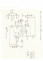
I like the F6 for its simplicity and the way the transformer is use as a phase splitter and came up with this schematic. And in trying to adopt a method to minimize the number of device actually use i remove the JFET feeding the final MOSFET in Michael Rothacher's Amazing circlotron's schematic
After that i realize i don't have a good way to create a feedback path since the original publish F6 is single ended; the bufferless balance input version didn't include loop feedback. So my thought was could one of the input primaries be use for feedback as shown in schematic below?
All comments welcome 🙂
Alex Oon
I have not really contributed much and have been mostly a passive participant . This would be my first attempt to start a discussion on an idea i have so please have some mercy on me.
I'll be building a F6 this year after postponing for about a year at the same time I getting a friend interested to DIY his own amplifier and I sort of selected the circlotron for him to build. Why circlotron? well mostly out of curiosity of its sound. Then my mind started thinking more and thought if there was a good way to combine the 2 so at the end of the build, i can compare F6, circlotron and a hybrid of the 2. I also bought a few SONY VFETs just before Nelson Pass showed it in his talk at Burning amp 2013.
I like the F6 for its simplicity and the way the transformer is use as a phase splitter and came up with this schematic. And in trying to adopt a method to minimize the number of device actually use i remove the JFET feeding the final MOSFET in Michael Rothacher's Amazing circlotron's schematic
An externally hosted image should be here but it was not working when we last tested it.
After that i realize i don't have a good way to create a feedback path since the original publish F6 is single ended; the bufferless balance input version didn't include loop feedback. So my thought was could one of the input primaries be use for feedback as shown in schematic below?
An externally hosted image should be here but it was not working when we last tested it.
All comments welcome 🙂
Alex Oon
I just realize the schematics aren't coming through very well if i link from my picasa web album.
Rev1 is my first attempt but could not quite figure out how to connect feedback loop
Rev 2 is my proposal on using one of the primary for feedback.
Alex
Rev1 is my first attempt but could not quite figure out how to connect feedback loop
Rev 2 is my proposal on using one of the primary for feedback.
Alex
Attachments
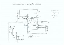
Just like F6, but with two feedback resistors, one from each side of the output????Not 100% sure it will work and a bit of a dangerous experiment.
Buzz,
Since the output is 180 degrees out of phase, summing the the 2 resistors in to one port, the 2 signals will effectively cancel each other.
Sent from my C6903 using Tapatalk 2
Since the output is 180 degrees out of phase, summing the the 2 resistors in to one port, the 2 signals will effectively cancel each other.
Sent from my C6903 using Tapatalk 2
Buzz,
Well since the output is 180 degrees out of phase, summing (resistor divider for each phase) with the output connected into 1 port, won't it results in no signal/0V being feedback since the exact center of the 2 output is 0V
Alex.
Well since the output is 180 degrees out of phase, summing (resistor divider for each phase) with the output connected into 1 port, won't it results in no signal/0V being feedback since the exact center of the 2 output is 0V
Alex.
Just like F6, but with two feedback resistors, one from each side of the output????Not 100% sure it will work and a bit of a dangerous experiment.
I found today this thread, let me make a question, ordinary the circlotron is a twin follower, this mean that the load is connected to the cathode or to the Source, in the case of Mr Rohacher, he connect to Drain. The output impedance is higher by 4 (?). But the Vfet-valve, has gain over one.
What happen with the curve trace? Is still a triode one or this is not related to the type of connection (G-S-D in common)?
Best REgards
What happen with the curve trace? Is still a triode one or this is not related to the type of connection (G-S-D in common)?
Best REgards
- Status
- Not open for further replies.