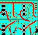
I'm drawing out a line-level input board, for the back panel of my preamp, using PCB-mounted RCA connectors and switch/select relays. The board will have gound floods on both sides and I had this idea that it might be good to have rows of stitching vias along the left & right tracks to hopefully reduce crosstalk (see attached pic - top fill omitted for clarity). However, I'm now second-guessing myself. My 'solution-statement' question boils down to (select one):
Other notes/questions: The ground planes tie all the input grounds and are single-wired back to the pre-amp's star-ground. Is it a bad idea to have the fills on both sides of the board? Also, the input-select relays will work the inverse way to most designs I see. The inputs are connected to the normally-closed contacts, so that all the non-selected input relays are energised, while the selected input relay is not - the idea being to reduce stray coil magnetic effects from the selected input. I know this is not a original idea, but thoughts?
Thanks
- This a good idea and will it decrease crosstalk and/or provide other interference advantages.
- Meh, may not help, but probably won't hurt.
- Forget it, could cause negative capacitance (or other) issues. Remove them.
Other notes/questions: The ground planes tie all the input grounds and are single-wired back to the pre-amp's star-ground. Is it a bad idea to have the fills on both sides of the board? Also, the input-select relays will work the inverse way to most designs I see. The inputs are connected to the normally-closed contacts, so that all the non-selected input relays are energised, while the selected input relay is not - the idea being to reduce stray coil magnetic effects from the selected input. I know this is not a original idea, but thoughts?
Thanks
Attachments
I first came across ground planes in old CRT TV tuner sections they were vital at VHF/UHF and although advocated by some in audio they never were my first choice.
What you are doing is providing two paths for the input whereas a single sided PCB has only one the component leg going through a hole and terminating in a single connection on the other side .
This provides a much shorter audio path at a sensitive input area and is more immune to pickup externally .
Sorry, but I don't understand? For the input (non-ground) lines there's only a single track each. For the grounds there are two possible paths, that's true, but why does that make it a longer path and what effect might it have?
(I'm not being argumentative here, just trying to understand). Thanks
(I'm not being argumentative here, just trying to understand). Thanks
Crosstalk on a planar circuit board between input or signal tracks is caused by two processes:
1. Capacitative coupling between signal tracks;
2. Return currents from sources sharing a common grand path (which can be left / right and/or input A / input B).
Tying the ground-plane through the board is unlikely to make much difference to either crosstalk mechanism.
You can remove capacitive coupling between two signal wires by printing a shield conductor in-between the signal wires; that way stray capacitance between the two conductor tracks is shunted to ground stopping the crosstalk. The shield track only needs to connected to ground at one end.
You can prevent common ground current paths by a properly implemented star-ground layout so that all grounds only connect together at a common point. For example, do not install RCA sockets on a ground-plane because all of the signal reutrn currents will become mixed together. (Current cannot flow without a voltage drop and so if a ground ground-plane has current in it it is no longer equipotential, and therefore not really a ground any more.)
The ultimate fix to prevent crosstalk between unused inputs and the selected input is to short the inputs at the input socket when not required. Done properly that eliminates both crosstalk mechanisms. Only the highest standard products need to go to that extreme because if both of the other suggestions are followed crosstalk should not be an issue.
Edit: looking at your layout the through board connections might help, but would work even better if they connected to continuous shield track on the same side as the conductor tracks. Do not make the mistake of mixing signal return currents in you ground-plane.
Last edited:
Crosstalk on a planar circuit board between input or signal tracks is caused by two processes:
1. Capacitative coupling between signal tracks;
2. Return currents from sources sharing a common grand path (which can be left / right and/or input A / input B).
<snip>
Do not make the mistake of mixing signal return currents in you ground-plane.
John makes several excellent points which I quoted. The last one is particularly critical, and most likely to be a problem in your implementation. If I am worried about it each channel will have a separate ground return to the star ground.
You should consider a re-design without a copper pour. Each input jack isolated and a straight connection to the relay, the gnd line exactly below the input track, so the opposite currents cancel the outside field, just like a coax.
Then the relay should switch both the input and gnd to 2 bus-lines, otherwise when you plug in your TV it will hum. Take another relay for the other channel, those contacts are close together and unshielded.
Keep the digital part away from inputs and bus lines.
Again treat the bus lines like the inputs with the gnd trace below, nothing should cross the lines, in case 0-ohm resistors.
go with the bus directly to the amp-part. Here you can use a plane but with consideration of each return current.
The many vias will make the board weak against bending and vibration.
Last edited:
Via stitching is for RF with controlled impedance traces, providing a constant impedance along a transmission line to prevent reflections, at audio frequencies its doing very little at all.
To prevent capacitive crosstalk distance between traces is much more useful, but if the impedances are low it may not be an issue at all.
Typical line level signals processed at impedances of 1k or so are not going to present an issue from inductive cross talk (inductances and currents too small), and only a small risk of capacitive crosstalk at the top end (for instance 1pF at 20kHz is 8Mohms equivalent, typically you can ignore this in low impedance signal path).
If you are handling signals at a high impedance like 100k then capacitive crosstalk is going to be more significant.
The main issue in a preamp with crosstalk is that from unselected inputs via the switching circuitry - this is much more objectionable than stereo crosstalk for instance.
Incidentally a groundplane in 1oz copper has a resistance of 0.5milliohms per square - this is often low enough to ignore except with a power amplifier. Basically a groundplane may work as well as star-grounding if the currents are all small - 1mA in 0.5milliohms is 0.5µV, or -126dBV. At 1k impedance that 1mA is a 1V signal, so the signal leakage is -126dB. With star-grounding its theoretically perfect, but you have to get the layout right! (disclaimer these back-of-the-envelope calcs omit details that may be important, best to measure to be sure)
Last edited:
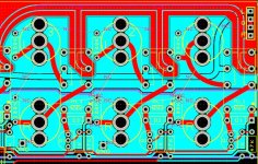
OK, Thanks for the responses from all. A lot of (sometimes conflicting 🙂) info here. So I've pulled some of the ideas here together, and propose the following compromises:
The pic here is a rough proof of concept of the above conclusions (still needs work, but you can get the idea).
Further comments? Agree/disagree?
Thanks again!
- Remove the vias. Wasn't too sure of this myself and that seems to be the consensus here too.
- Remove (most of) the top fill. Split the bottom fill into two (top & bottom, left and right inputs). Wire those two separately back to chassis/star ground. (Too many practicality issues to wire every input ground back to the star 🙂)
- The 'left' bottom fill will also have the effect of paralleling the left bus tracks & providing johnmath's 'shield tracks'.
- Shrink the top fill to just around the right bus tracks, also providing the 'shield tracks' for them. Tie that back to the same pad for the right fill wire to star ground.
The pic here is a rough proof of concept of the above conclusions (still needs work, but you can get the idea).
Further comments? Agree/disagree?
Thanks again!
Attachments
....hopefully reduce crosstalk...
How many sources do you have playing at once?
How many sources do you have playing at once?
I was talking about L+R channel crosstalk. As I said:
[...] Most of the time other sources will not be on at the same time anyway,
I admit hadn't even thought about multiple source xtalk, until folks brought that up here.
I agree with most of the points already made. I don't use copper pours for audio for ground planes, I do use them for large power bus on power amps.
I found a strange problem when I used a ground plane on a preamp, it picked up hum, traced to the ground plane running under a power supply capacitor, so don't do that. 🙂
I found a strange problem when I used a ground plane on a preamp, it picked up hum, traced to the ground plane running under a power supply capacitor, so don't do that. 🙂
- Home
- Source & Line
- Analog Line Level
- Input board w/rows of vias to reduce crosstalk... Good idea? Or bad idea?