Hi,
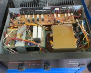
I just got this amp in very good condition. I liked its sound but I hear some noise when I close to the speakers (102dB sensivity) on both channels, even though amp specified as 105dB S/N ratio. I don't hear any noise from my Kenwood KM-106 amp (120dB S/N specified) with same speakers. Is this expected from such a big amp even though reasonable specs? or should I worried with something?
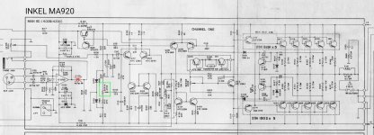
What is the purpose of the SVR114 pot? Is it for adjusting the DC offset which is around 10-15 mV on both channels.
Can I omit C108 NP dc blocking cap, (if the opamp offset is low) since there is another one (C110) next to it ?
Regarding the topology and the schematic, is there anything that can be improved? Any comments and suggestions?
Thanks in advance.
I just got this amp in very good condition. I liked its sound but I hear some noise when I close to the speakers (102dB sensivity) on both channels, even though amp specified as 105dB S/N ratio. I don't hear any noise from my Kenwood KM-106 amp (120dB S/N specified) with same speakers. Is this expected from such a big amp even though reasonable specs? or should I worried with something?
What is the purpose of the SVR114 pot? Is it for adjusting the DC offset which is around 10-15 mV on both channels.
Can I omit C108 NP dc blocking cap, (if the opamp offset is low) since there is another one (C110) next to it ?
Regarding the topology and the schematic, is there anything that can be improved? Any comments and suggestions?
Thanks in advance.
Attachments
Last edited:

Probably not a good idea to short C108, since the volume pot could get noisy.
If you burn the unit in for a while, the noise may lessen some. Did you short the inputs when checking the noise level?
Check all the output stage emitter resistors in-circuit, and check the bias per the manual for 10mV across each resistor.
Your meter must be able to measure 10mV accurately to do this. Also check the output DC offset and adjust per the manual.
Attachments
Last edited:
Hi @rayma,Probably not a good idea to short C108, since the volume pot could get noisy.
If you burn the unit in for a while, the noise may lessen some. Did you short the inputs when checking the noise level?
Check all the output stage emitter resistors in-circuit, and check the bias per the manual for 10mV across each resistor.
Your meter must be able to measure 10mV accurately to do this. Also check the output DC offset and adjust per the manual.
Thank you for the correct service manual with the adjustment instructions.
Yes I did short the inputs, no effect on the noise.
Regarding the bias, measured values variy between 10mV and 15mV even though emitter resistor values are the same (1 ohm). So I did make sure that minimum is 10mV which makes other ones varies between 10 and 15mV.
I did adjust DC offset per manual and it is ok now.
I will keep the amp ON for while for the noise. I guess it's already got low a bit already.
Thank you.
If it has been out of use for a while, it should work and sound better after it breaks in.
Since it seems to work ok, I would avoid further tinkering with it, which could cause problems.
Since it seems to work ok, I would avoid further tinkering with it, which could cause problems.
You're right about the voltage. Amplifier supplied with 2x98v rails but the 2SC3281/2SA1302 rated at 200V Vceo. Quite disturbing. This is maybe the why pre drivers KTC2238/KTA968 runs hot.You can change TL072 with a more modern lower noise jfet op- amp.
Inkel amplifiers used to have the power supply around the maximum allowed voltage in the datasheet by the power transistors.Maybe the filter and / or decoupling capacitors may need to be changed as well.On the other hand very sensitive speakers aren' t a good match to such high power amplifiers.
I use unbalanced TRS input which mechanically isolates the opamp from the signal chain. I will take a look around the opamp as well. Thank you.I' d check also the state of the solder around the zenner diodes pins regulating the op amp supply d101, d 102 , also R120 and R121 solder and state cause they might have been run hot for over 30 years by now and change the decoupling caps around it c104, c106 with some good quality ones.
Possibly, but Inkel , unlike other amps I' ve seen is using very high supply voltages, almost the same with professional stage power amps , but with lower power voltage transistors.They sound very well as they successfully fight Early effect, but they break in flames ...I remember having one for repairs decades ago and couldn' t find original matched transistors so it never worked again as all the transistors were fried.
So, if I have to replace the output transistors of this particular design, should I choose 200V or 230V (or higher) types of power transistors according to their strategy against Early effect? E.g: MJL3281A/MJL1302A (200V, 200W) vs NJW3281G/NJW1302G (250V , 200W)? Must I stick with the original design principles as much as possible in order to satisfy the sound quality concerns?
Last edited:
Btw, this amplifier performs unexpectedly well... it is impressive to be honest. Highly musical, highly detailed and yet powerful. What I liked the most is its crisp sound signature and its authority over the speakers.. Crystal clear highs, outlined and well defined mids and lows. I think that this unexpected sound comes from the design decisions of the engineers. Quite impressive for a 30-35 years old design.
@jenimitso
I consider some good opamps like opa2192 and opa1612. I will also consider recapping using quality capacitors, especially the ones at the signal path. Amp already sounded beyond my expectations so I have to improve it to be more reliable rather "better sounding" with these improvements.
Thank you for reminders regarding thermal regime and the 4 ohms load. I will update the thread as I progress.
Can anyone comment on C123 and C124? Are their purpose is DC bypass or AC coupling? If I replace them with some Non-polar Elna Silmics can I get any benefit? C124 directly connected to R145 emitter resistor and its value is 0.68 ohm instead of 1ohm like all others. Is this purpose or schematic error?
I really appreciate to anyone comment on this topology in general. Maybe some improvement advices regarding component values and selection?
I'm collecting parts for recapping. I plan to replace all ceramic capacitors with NP0/C0G ones. I will also replace heat insulators with alumina ones.
I really appreciate to anyone comment on this topology in general. Maybe some improvement advices regarding component values and selection?
I'm collecting parts for recapping. I plan to replace all ceramic capacitors with NP0/C0G ones. I will also replace heat insulators with alumina ones.
- Home
- Amplifiers
- Solid State
- Inkel MA-920 help