I have a couple of 500VA transformers that have a center tapped 62-0-62 secondary and a single 115VAC primary. The secondary voltage is a little too high, and I would like to reduce it by around 5-10%.
Thanks to this Wikipedia article, I see that a voltage divider can be created with two inductors.
Can I simply add an inductor in series with my transformer primary to form a voltage divider, thus reducing both primary and secondary AC voltage? Will the inductance of the primary change with the amount of current drawn? Are there practical pitfalls/problems with this approach?
Last edited:
I reckon you'd be better off removing turns from your secondaries. An inductor would reduce the off-load output voltage (say it was 10% of the magnetization inductance) but given the high values of primary inductance of mains trafos, you'll need a fairly big one (my guess - of the order of 1H). Then it'll need to be able to handle the max load current (say 5A) without saturation. Looks highly unlikely you'll find a suitable inductor at less than the cost of a new trafo with the appropriate secondary voltages.
1H??? Really? That would mean the transformer primary inductance is on the order of 10H. Is that right?
Well I've not measured a 500VA trafo but I could do that and report back as I think I have one next door. So let me fire up my LCR meter.....
It turned out the one I have is a 1kVA toroid, it measured 2.9H at 1V excitation. Generally the inductance increases with higher excitation (mains here is 220V). A 500VA trafo will have higher inductance than my 1kVA. So 10H turns out not to be such a bad guess for your trafo, its probably within 6dB.
<afterthought> No, I'm overly optimistic - your mains is 115V so your inductance will be lower. Probably between 2 and 5H.
There's another problem I forsee with the series L approach to voltage reduction. The L forms an LR low-pass filter in conjunction with the load impedance which isn't likely to be purely resistive nor will it be constant. So I reckon you'll impact your transformer's regulation negatively.
Last edited:
*sigh* well it seemed to have some good potential initially! Oh well, I will just have to buy some amp modules that can use +/-90V rails after all...
You don't like choke input, you were going to use a choke anyway? I can't think of a better excuse. Just my  , where size/weight aren't an issue they make such a good supply, regardless of type.
, where size/weight aren't an issue they make such a good supply, regardless of type.A poor idea.
To begin with rather than plain reducing voltage by a fixed amount it will jump wildly following current consumption.
Then it won't be easy to find the proper inductors and custom winding them will cost as much as the transformer you are trying to "save" or more.
Only real solution, if possible, is to add 10% extra turns to primary, but that also is a lot of work: disassembling the transformer, winding, reassembling.
Or you could use a bucking transformer.
Even better: get a design which can run out of those higher rails.
Instead of an inductor, you can use this electonic voltage reducer:Can I simply add an inductor in series with my transformer primary to form a voltage divider, thus reducing both primary and secondary AC voltage? Will the inductance of the primary change with the amount of current drawn? Are there practical pitfalls/problems with this approach?
http://www.diyaudio.com/forums/powe...-elegant-insane-way-converting-220v-110v.html.
It is adjustable, and won't degrade the supply's internal resistance, the opposite in fact. It will also let the transformer run cooler.
Main drawback, the output waveform is somewhat "disturbing", visually, but if it works, who cares?
I have a couple of 500VA transformers that have a center tapped 62-0-62 secondary and a single 115VAC primary. The secondary voltage is a little too high, and I would like to reduce it by around 5-10%.
Thanks to this Wikipedia article, I see that a voltage divider can be created with two inductors.
Can I simply add an inductor in series with my transformer primary to form a voltage divider, thus reducing both primary and secondary AC voltage? Will the inductance of the primary change with the amount of current drawn? Are there practical pitfalls/problems with this approach?
The drop of an inductor depends on the current, which is not constant, so it is not a solution.
The best and simplest solution: wind some turns on the transformer, and add them to the primary. (How many turns? Measure voltage/turn with 1...10 turns, and you can calculate for yourself, but approximately 20 turns needed for 5 %.)
since you only want to reduce the voltage only by 10% the best non-invasive method use a "bucking' transformer. you can use a smallish filament transformer rewired to drop the primary voltage.
rewinding your transformer primary is usually a non-starter esp. for a toroid, the secondary is the outer windings. For EI cores removing laminations are a rework nightmare in themselves even if you luckily have a split bobbin.
rewinding your transformer primary is usually a non-starter esp. for a toroid, the secondary is the outer windings. For EI cores removing laminations are a rework nightmare in themselves even if you luckily have a split bobbin.
Not always.................... for a toroid, the secondary is the outer windings..................
I reported some years ago a commercially bought toroid with the Primary on the outside and the Secondaries on the inside.
So far this is only 1 of 50 that is inside out.
But that does not stop one adding 20 to 30 turns around the outside and insulating that very well ready to add in series with the main Primary.
Now apply the Mains voltage to the new 30T+ Primary and the output voltage should be reduced. If it is increased then swap the phase of the added turns.
Adding a series inductor will ruin regulation. Don't do that.I have a couple of 500VA transformers that have a center tapped 62-0-62 secondary and a single 115VAC primary. The secondary voltage is a little too high, and I would like to reduce it by around 5-10%.
Thanks to this Wikipedia article, I see that a voltage divider can be created with two inductors
The best option is to remove few turns on the secondaries.
Or you can add few turns to the primary winding. Requires thorough isolation.
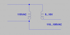
If for some reason you do not want to mess with all that stuff: find 115V to 6-12V / 4.5A+ transformer, connect it like on attached pic.
Attachments
1 of 50 that is inside out.
custom transformers often have the pri wound in advance waiting on the shelf for orders,
in North America modern toroids often have dual primaries operating in parallel, so winding phase and balance becomes key. I prefer deconstruction of the secondary, then I don't have to stock a lot of the magnet wire sizes and sweat over the hi-pot test failures of the added 4 more primary leads. BTW most DIYers don't have access to equipment used to test for dielectric testing of the cheap tapes they might happen to choose. so not a good idea to modify the primaries!
Last edited:
I have read the same. I have never bought any.custom transformers often have the pri wound in advance waiting on the shelf for orders, ..........
There are a few retailers that will sell the primary+insulation on a toroid.
They tend to be expensive, (that's probably why I never bought any).
For the EU a pre-wound 230Vac primary for each size of core would massively reduce the stock to cover all options. That reduced stock-holding should make them very cheap !
, connect it like on attached pic.
the one phase needs to be reversed on your image, its really hooked up like an autotransformer. "bucking" is the wrong term.
I don't like "bucking" either.
That implies connecting the extra turns out of phase to REDUCE the output voltage. But that brings with it a lot of extra copper that makes regulation worse and increases heat inside the transformer.
It would be a lot more efficient to remove secondary turns because that is what "bucking" does, it electrically removes the effect of some of the existing Turns.
I don't like "bucking" either.
.
bad names often throw good people in momentary chaos.
I sometimes wrongly use it simply because more people recognize the principle, but the details need to be straighten'd out.
Last edited:
The auto-transformer can be used to efficiently transform upwards, or to transform downwards.
It just depends on whether the primary side uses the extra turns giving a reduced output/secondary voltage.
Or when the extra turns are in the secondary, one gets a higher output voltage. In this case the mains is connected to the original primary.
No need for any "bucking".
It just depends on whether the primary side uses the extra turns giving a reduced output/secondary voltage.
Or when the extra turns are in the secondary, one gets a higher output voltage. In this case the mains is connected to the original primary.
No need for any "bucking".
If you reverse one of the winding then you'll end up with output voltage higher than input voltage while the opposite is needed.the one phase needs to be reversed on your image, its really hooked up like an autotransformer. "bucking" is the wrong term.
- Status
- Not open for further replies.
- Home
- Amplifiers
- Power Supplies
- inductor in series with transformer primary to reduce secondary voltage?