Hello.
I've been told to separate and right-angle-mount crossover inductors because if one doesn't do so, they act as transformers and couple each others' signal.
Has anyone ever encountered or heard of any such coupling happening between inductors and other components such as wirewound resistors or film-foil capacitors? If they can make an inductor with film and foil it makes sense that a film-foil capacitor could act as an unintended transformer winding as well.
My crossover frequency is low, so the parts are pretty big.
Thank you kindly.
After much pondering I recently bought a pair of LS50s. When they finally arrived after being back ordered forever, the sound quality certainly lived up to expectations, but the left one buzzed audibly. It wasn't very loud, and certainly not bothersome, but it was much noisier than the power amp should have been.
I finally figured out that it was because it was perched on top of the power amp (in my desktop nearfield setup) and one of the crossover inductors was picking up the field from the power transformer. The speaker still buzzed when disconnected from the amp, but only if the terminals were shorted together.
So I think it is quite possible that crossover magnetics could couple to each other. The effect would be small errors in the frequency response.
As for an inductor coupling to a capacitor, I don't think that is an issue. The mutual inductance between the capacitor and another coil must be less than the ESL of the capacitor, which is usually a few nanohenries only. Good quality capacitors are wound and connected in such a way that the inductance of the rolled-up foil cancels.
Last edited:
I posted a few days ago about inductance coupling.
Some well respected Members came back and rubbished the idea that inductances at normal spacing affect each other.
Whereas D.Self has a section in his power amplifier book about inductor coupling.
AND
we have advice from hundreds of designers and builders that orientation of inductors is important to getting crossovers to work as designed.
It all depends on the definition of "normal". Self was investigating crosstalk between the Zobel inductors in a stereo amp. Even a minuscule amount of coupling will dominate the HF crosstalk performance of a well-designed amp. It would take a lot more coupling to affect the frequency response of a crossover audibly, if not measurably. I'm sure it could be done if you tried hard enough, like stacking air-cored coils right on top of each other.
The noise floor of my valve hifi amp is limited by the hum field from the power transformers coupling directly into the OPTs. The original designer put them a bit too close together.
The noise floor of my valve hifi amp is limited by the hum field from the power transformers coupling directly into the OPTs. The original designer put them a bit too close together.
As long as the inductors are air-cores, you can lay all of them down flat as long as the distance between the perimeters (not the centers) of adjacent coils is 2 inches; the mutual coupling is very small (-50 dB). If you have more room you can space them further apart, but if you have less room, then some will need to be oriented differently. Coupling from an inductor to a capacitor is virtually non-existent. I performed extensive tests on both issues and documented them on the Parts Express Tech Talk forum under my user name of Paul K.
Paul
Paul
I was taught that the "safe" distance for air core inductors is 2.5 x largest dimension if oriented in the same axis...so absolute distance is dependent on core size.
My tests and experiments, which replicated and expanded upon those by others documented in published articles, clearly showed that the sizes of the inductors were not a significant contributor to mutual inductance or voltage crosstalk. In my testing I used large inductors "paired up" with much smaller inductors, regarding both inductance and physical size, as well as pairs of inductors of the same size and inductance. In the end, though, if you are so inclined and don't have space limitations, spacing inductors further apart certainly won't hurt, but 2 inches is entirely acceptable.
Paul
Paul
I was taught that the "safe" distance for air core inductors is 2.5 x largest dimension if oriented in the same axis...so absolute distance is dependent on core size.
I posted a few days ago about inductance coupling.
Could you tell me how to find that? I did a few searches here about those terms and I didn't find much of anything.
Thanks
And oh by the way, the major issue at hand is placing a big wound capacitor right up next to a big wound inductor, perfectly as if you were deliberately trying to make a transformer...
It would make the board lay out nicely but if it's a performance problem then that's not what I should do.
It would make the board lay out nicely but if it's a performance problem then that's not what I should do.
One of the many tests I ran had a large capacitor oriented right through the middle of an air-core inductor with the inductor "energized". Results? The capacitor didn't care one iota.
Paul
Paul
And oh by the way, the major issue at hand is placing a big wound capacitor right up next to a big wound inductor, perfectly as if you were deliberately trying to make a transformer...
It would make the board lay out nicely but if it's a performance problem then that's not what I should do.
One of the many tests I ran had a large capacitor oriented right through the middle of an air-core inductor with the inductor "energized". Results? The capacitor didn't care one iota.
Paul
Well, that's certainly something.
My tests...
FWIW, here are links to the two threads I started at PETT in 2013 that dealt with tests/experiments I conducted on inductor spacing and inductor-capacitor "spacing".
The first: My take on inductor spacing
The second: Crosstalk measurements between inductors
Paul
FWIW, here are links to the two threads I started at PETT in 2013 that dealt with tests/experiments I conducted on inductor spacing and inductor-capacitor "spacing".
The first: My take on inductor spacing
The second: Crosstalk measurements between inductors
Paul
One of the many tests I ran had a large capacitor oriented right through the middle of an air-core inductor with the inductor "energized". Results? The capacitor didn't care one iota.
Paul
There are a couple of issues with caps of certain structure in this case, but few will care.
The Obbligato Gold, Jantzen Z-Superior and Z-Silver caps (for example) all are constructed within an aluminum tube. This tube can become a 'short-turn' in close proximity with a coil and actually make the coil value smaller than spec. Any metal-shelled caps are subject to this issue.
Troels also had a test with caps close to coils to see, and he found Silver Micas, even though we typically do not use them in xovers due to small value, are of the same kind of detriment as having a conductive metal shell.
Panel-Mount resistors are in an aluminum heatsink case, and these can also become a shorted turn to a degree.
Other than that I know of no issues with regard to spacing of passive xover components.
Later,
Wolf
go to search - advanced.Could you tell me how to find that? I did a few searches here about those terms and I didn't find much of anything.
Thanks
enter my name - coupling - in last 2weeks - posts.
Returns just 5 results one of which is this Thread. Only 4 results to look at.
But because they argued against the idea of inductive coupling, I gave up and left them to their own opinions, since I don't have the equipment to measure and show data.
D.Self proves the inductive coupling for isolated two coils. Yes, he is looking at inter-channel crosstalk, but his results PROVE there is coupling. This seems to loosely fit with the 2" gaps talked about earlier and with the long standing advice on inductor orientation and on inductor susceptibility to adjacent metal panels, also mentioned above.
BTW,
the "transformer" driving an Audax HD 3P is just two close coupled air cored coils.
Last edited:
It wouldn't be good to mount a capacitor within a coil IMO, for the reason that wolf-teeth mentions.
But the worst components for interacting are inductors.
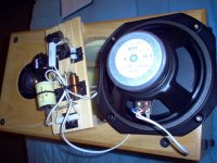
They interact with each other and a circuit board. Below is an equivalent of a 1mH coil mounted on a ground-plane circuit board. It not only interacts with the circuit board aka ground-plane (silver ashtray) to reduce the effective value by about 20%, but sends an audible high pitched whine to the tweeter filter unless you mount coils at right angles and good distance. I am using a sophisticated Multimeter with an inductance (mH) scale. You should possess one IMO.
I should mention that an inductance meter works by sending a 1-2kHz test tone to the component and calculating the back emf, which is what you hear through the cone tweeter in this case.
For this reason, I use point to point wiring and right angles and distance. 🙂
But the worst components for interacting are inductors.
They interact with each other and a circuit board. Below is an equivalent of a 1mH coil mounted on a ground-plane circuit board. It not only interacts with the circuit board aka ground-plane (silver ashtray) to reduce the effective value by about 20%, but sends an audible high pitched whine to the tweeter filter unless you mount coils at right angles and good distance. I am using a sophisticated Multimeter with an inductance (mH) scale. You should possess one IMO.
I should mention that an inductance meter works by sending a 1-2kHz test tone to the component and calculating the back emf, which is what you hear through the cone tweeter in this case.
For this reason, I use point to point wiring and right angles and distance. 🙂
Attachments

Last edited:
Thanks, Andrew, I'll go look.
Well, yeah, but my concern is that everything on the circuit board is pretty much an inductor. The wire wound resistors are built exactly like inductors, just more spaced out. The capacitors are built exactly like those highfalutin' foil inductors. If you didn't know what the parts were called and you looked at them with your x-ray vision, you'd think that they all did the same thing.
It wouldn't be good to mount a capacitor within a coil IMO, for the reason that wolf-teeth mentions.
But the worst components for interacting are inductors.
They interact with each other and a circuit board.
Well, yeah, but my concern is that everything on the circuit board is pretty much an inductor. The wire wound resistors are built exactly like inductors, just more spaced out. The capacitors are built exactly like those highfalutin' foil inductors. If you didn't know what the parts were called and you looked at them with your x-ray vision, you'd think that they all did the same thing.
I would expect that a pair of capacitor plates wound as coils will have a significant inductance.
I expected that the lead outs would tap into different layers of the windings to reduce the inductive effect.
I recently dismantled a damaged, cheap, commercial quality and very ordinary electro.
I found, but not surprised, it has just one tapping for each plate. It had riveted aluminum tags to the etched aluminium foils and the aluminum tags were welded to the solderable lead outs.
But the wound coils are inside a metal can. They should be oblivious to an external field.
The inductor coil will not be oblivious to a metal can inside it's coil. Just about every body, with audio design credentials, advise strongly against leaving metal inside an air cored inductor coil. Iron and nickel would be the worst offenders, but all metals will have at least some effect.
Last edited:
I don't particularly recommend mounting a capacitor within a coil, but some people, like Wolf, end up with crammed crossover assemblies that must be mounted inside a pretty small box. According to the tests I ran, most capacitors will not be bothered in the least if mounted in the middle of an air core inductor, and Wolf's comments indicated essential agreement with this (in fact, I ran those specific tests at Wolf's request).
I'm not sure of the importance of your ground plane test as described below. I don't think many DIYers use copper-plane circuit boards for their crossover assemblies but do use point-to-point wiring and as much distance as available between components, as well as appropriate component orientation.
I will repeat my position: if you have the room, spread out inductors as far as you want, even orient them at right angles if desired, but the practical reality is that a 2-inch spacing between the coil perimeters of air-core inductors all laid down flat is completely acceptable, and there are likely going to be far larger problems to worry about from an audibility standpoint in a speaker design.
Paul
It wouldn't be good to mount a capacitor within a coil IMO, for the reason that wolf-teeth mentions.
But the worst components for interacting are inductors.
They interact with each other and a circuit board. Below is an equivalent of a 1mH coil mounted on a ground-plane circuit board. It not only interacts with the circuit board aka ground-plane (silver ashtray) to reduce the effective value by about 20%, but sends an audible high pitched whine to the tweeter filter unless you mount coils at right angles and good distance. I am using a sophisticated Multimeter with an inductance (mH) scale. You should possess one IMO.
I should mention that an inductance meter works by sending a 1-2kHz test tone to the component and calculating the back emf, which is what you hear through the cone tweeter in this case.
For this reason, I use point to point wiring and right angles and distance. 🙂
A wound foil capacitor is completely different to an inductor. Even if the foils were only connected to the terminals in one place, the current goes out on one foil and returns on the other foil in the opposite direction, so the magnetic field cancels and the winding doesn't act as an inductor.
Further, any self-respecting audiophile grade capacitor would use extended foil construction where contact is made along the whole length of the edge of the plate. The current flows straight from one end of the capacitor to the other, and the inductance (both self and mutual) is about the same as an inch or two of wire.
Wirewound resistors are a different matter. I have seen big ones used as Tesla coils, shooting sparks from one end.
- Home
- Loudspeakers
- Multi-Way
- Inductive interactions among Crossover Components