How to measure?
I am checking different primary wired, 8,5k 10k and 14k to 211 tube, but I am not sure how to measure and how to screw,
1º if screw not too hard both part can be move E I only the magnetic field close both part.
2º screw very strong that can not move both part E I
well to measure inductance depend if apply pressure or not with pressure on E I inductance increment to reduce the air gap thick.
Are you trying to vary the gap on the core and measure the inductance with various gaps? Is this a diy opt or have you bought opt where the cores are loose?
I use the same core but I change three different the coil with different internal structure and primary impedance. I want to measure without connect the B+ ( 1200v ) I am not sure how to screw with movement between E I or not.
If you omit the current source, wouldn't that increase the inductance, i.e., not its intended use in a SE amplifier? Also why do you use such HV (4.9kV) for the current source?
If the core is set why are you talking about screwing around?
What kinds of test equipment do you have? Not an LCR meter I guess...
Do you have a scope and a signalgenerator?
What kinds of test equipment do you have? Not an LCR meter I guess...
Do you have a scope and a signalgenerator?
Sorry maybe I explain very bad, when you close the E I in the transformer you can scew with presure over betwen E I or without in this case the I is not too lock you can move with the finger over 0.6mm, if I screw very strong is totaly lock. I check others OPT and I have seem that are totaly lock, I will do in the same way to begin.
To measure I have both scope and generator a litle old but enought.
To measure I have both scope and generator a litle old but enought.
Also bear in mind that when DC current is applied, the E & I sections will come together and squeeze the air gap closer with or without the "lock". So you should make the measurement under realistic operating conditions, i.e., not at low AC swing, without DC current and without "lock".
how to measure inductance under dc-bias --> try this ...
req: simple method to measure L under DC bias
req: simple method to measure L under DC bias
You can measure exactly the L and frequency answer with thd vs freq ( if you have a right test set) In the picture there is specified the load of 6 ohm driven by a ss amp On secondary ( primary in the real circuit) there is 2500 ohm This because the dut has a 1:20 ratio You have to arrange for your needs In this way you have a big swing on the primary Th OT trafo is a reverse stuff and this is the perfect test You can omit the current source for I bias without any interference on measurement I will resend the diagram done with and without bias current
Walter
Walter
You can measure L with an LC meter.
If you have just a scope then put a 1k resistor in series with a 100nf capacitor in series with primary winding. Apply a sine wave to resistor and other end of primary. Wind up and down frequency until a minimum across the LC and this is your resonant frequency.
Use formula:
L=1/ ( 4 pi squared F squared C)
Where F is resonant frequency. C= capacitor value and pi = 3.142 and L is inductance.
Yes, but the result is only valid for low level signal, and not going to give you a full or accurate picture... as the inductance changes with the frequency and the drive level. Lp is important for the LF response, so measuring the inductance with low level signal at mid-frequency really is not that informative.You can measure L with an LC meter.
Then use the second method I gave. You can change the capacitor to give a different frequency. You can also change the sine wave magnitude to test out higher voltages.
This is how I measure SMPS transformers.
This is how I measure SMPS transformers.
If you want to measure the specs at 1 watt on 8 ohm and the OT trafo has 1:20 as ratio you need on primary 56 vrms and it is not easy. From 20 to 20 khz (minimum) Then the primary must see a reasonable load similar to an Rp of the tube Only in this way you can check the real performance
Walter
Walter
Last edited:
Celsius, is this an SE or PP output transformer ? If it was an SE transformer then you would need to operate the primary winding at the idle current when measuring inductance.
Link to a reasonably simple test technique that allows DC current and AC voltage to be modified to take spot inductance measurements at twice the mains frequency using a simple power transformer secondary as the excitation. I've also used it for PP output transformers to show inductance droop with idle current imbalance.
https://www.dalmura.com.au/static/Choke%20measurement.pdf
Hi
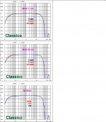
in attached some diagram that I sent here time ago.
As you see there are different freq. answer from test set I described before also with 0 mA of bias.
They are a test related only to the trafo without the tube.
With the tube they may be different considering the internal charatherstics of each one tube used.
In this way you can have, with proper instuments, exactly the L of the OT trafo
Walter
Attachments
Yes, but the result is only valid for low level signal, and not going to give you a full or accurate picture... as the inductance changes with the frequency and the drive level. Lp is important for the LF response, so measuring the inductance with low level signal at mid-frequency really is not that informative.
L increases with rising excitation and decreases with rising frequency - within limits of course. LF is where L matters most, so why not use mains frequency 50/60Hz.
As the OP just wants to evaluate the effect of bigger or smaller air gap (more or less compressed E-I core), the simplest method for his purpose might be to use an isolation trafo from mains - say 48v @ 50Hz, measure ac voltage across L and ac current into L with a multimeter, get impedance Z=U/I and calculate L=Z/(2*pi*f).
This ignores dc resistance and saturation by dc current but might be good enough for a relative comparison.
To study influence of excitation, use a 1:1 isolation trafo + variac.
To improve accuaracy subtract dc resistance from Z (not quite correct but close).
Last edited:
I think is better finish the amp and measure in real condition, to try to measure with same maybe is not a good way, maybe is ok or not, I think that will be more conclusive to measure the range frequency in real condition on 8ohm secondary load.
thanks for your replies
thanks for your replies
to Celsius In my opinion the first step is to understand which kind of trafo you have. Then you can test the entire amp. The problems are two, as you know The L at low frequency that became low mainly for the core and winding and same happen for high freq. due to parasitic In both case the frequency answer decrease and ( more important ) the Thd vs freq. also increase This because the tube can't delivery the right current due to the non appropriate coupling at the ends fo the spectrum. If you have exactly in which way the trafo is running you can understand what happen with a specific tube.
Walter
Walter
L increases with rising excitation and decreases with rising frequency - within limits of course. LF is where L matters most, so why not use mains frequency 50/60Hz.
Yes, that's a good way to do it without signal generator or power amplifier as Walter proposed.
- Status
- Not open for further replies.
- Home
- Amplifiers
- Tubes / Valves
- inductance in OPT