I've been thinking of getting around to designing a circuit like this for a while. A way of increasing the output power of MOSFET amplifiers by mitigating the effects of the threshold voltage in vertical output stages, and the effects of the low transconductance in lateral output stages 🙂 . Without the need for an extra transformer or any of that nonsense.
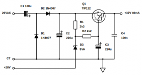
In order to get the most power out of MOSFET output stages, the drive voltage needs to be 4-6 Volts (depending on the supply rail, type of MOSFETs, etc.) higher than the supply used by the output stage. By using a voltage doubler off the main transformer, followed by a simple regulator which uses a Zener diode to provide a fixed reference voltage above the output stage supply rail. This can then be AC coupled to ground with a fairly large time constant (0.5s or so), which has the extra advantage to greatly reducing the usual thumps and bangs heard through the loudspeaker as the amplifier is turned on, as the usual ripple decoupling capacitors downstream are no longer needed 😀 .
I've only drawn the circuitry required for the positive supply rail, the negative rail will simply need to be a mirror of the positive version, with the complementary PNP darlington package (TIP127 in this case) and the polarity of the electrolytic capacitors and diodes reversed.
With this arrangement, it is possible to bring an amp using ALFET lateral devices that would otherwise only reach 30WRMS up to a respectable 42WRMS, with no modification to the power transformer!
Attachments
In a lateral output stage using MosFET output transistors this is already achieved by the use of a boot strap capacitor. Your circuit is incorrect as the zener is upside down.
In a lateral output stage using MosFET output transistors this is already achieved by the use of a boot strap capacitor. Your circuit is incorrect as the zener is upside down.
I'm afraid that you are quite wrong, sir 😉.
A bootstrap capacitor only increases the drive above the rail on the positive side (if an NPN device is used for the VAS) on the negative side, it is still limited to the power supply rail minus the collector emitter voltage of the VAS transistor on the negative end of it's operation.
The Zener diode is the right way around. It creates a reference that is an addition of it's breakdown voltage, and the output stage supply rail.
Also you use 'MOSFET' instead of 'MosFET' as in 'Metal Oxide Semiconductor Field Effect Transistor' 😀.
I don't think the zener is upside down. It will give a voltage of 28+5.6 at the base of Q1. You might need higher than 5.6 to overcome the double vbe drop of the Darlington though.
I don't think the zener is upside down. It will give a voltage of 28+5.6 at the base of Q1. You might need higher than 5.6 to overcome the double vbe drop of the Darlington though.
Well, for an 8 Ohm load driven from a lateral output stage with a transconductance of 1S, you need drive voltage of 31.5V to realise the full potential swing of the output stage. An elevation of 3.5V in total.
28V (OS power rail) + 5.6V (Zener voltage) - 1.2V - 0.15V (the drop across R2) = 32.25V
This is more than enough, even if it is only a relatively small increase. If you were to increase the voltage, then you would start to get problems with 'rail-sticking' as the amplifier clips.
Apologies, I misread the circuit assuming you were referring to the output stage of an amplifier, as per your text reference, not the power supply.
Fair enough 🙂 The values and voltages look reasonable.
It's not particularly exotic, I'm afraid. So long as it does the job 😀 !
- Status
- Not open for further replies.
- Home
- Amplifiers
- Solid State
- Increasing MOSFET amplifier output power - a VAS supply elevator