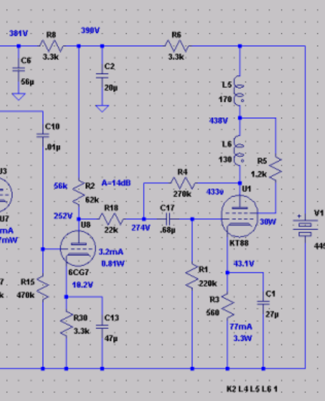
I have this power amp and I really love the sound however the sensitivity is pretty low. I am wondering about ways to increase the sensitivity without messing up the sound.
Thoughts I had were
1. Eliminate (jumper) R18.
2. Change 6CG7 to 6AQ8. (not sure whether increased gain would be swamped by the FB).
3. Increase R4.
Any suggestions?
Thoughts I had were
1. Eliminate (jumper) R18.
2. Change 6CG7 to 6AQ8. (not sure whether increased gain would be swamped by the FB).
3. Increase R4.
Any suggestions?
Attachments
I like the way a 300K R4 sounds in the Blueglow KT88 amp I built. Not sure what R18 is even there for... 0.68uf seems high for the coupling cap too, a 0.22uf with R1 at ~470K might also help.
I can't find R18 in the schematic,, I guess it appears into the resitor network at the input valve.
Sure you could use the 6AQ8 and almost doubling the gain at the 2nd stage but you should recalculate Ra/Rk, also 6CG7 is more linear and suitable for driving that power tube
Sure you could use the 6AQ8 and almost doubling the gain at the 2nd stage but you should recalculate Ra/Rk, also 6CG7 is more linear and suitable for driving that power tube
That all makes sense. I will have to check the actual final value of that cap I think it may well have been reduced. R18 was an attempt to increase the output impedance at the junction of the FB resistor due to the low Rp of the 6CG7.I like the way a 300K R4 sounds in the Blueglow KT88 amp I built. Not sure what R18 is even there for... 0.68uf seems high for the coupling cap too, a 0.22uf with R1 at ~470K might also help.
At the time I was taking inspiration from Kegger's design and Abdellah as well. Initially I was looking at using 12AU7 but selected the 6CG7 for linearity at the expense of mu. My next project is a preamp so I can just make one with a touch more gain but just thought I would look into whether there is a reasonable way to increase the gain of this PA.I thought the SEUL KT88 was a 2-stage amp with a triode strapped pentode driving the KT88?
jeff
Your output stage gain is set by the Schade feedback network:
Schade feedback resistor from the KT88 plate
RL of the driver tube, in parallel with the driver tube plate impedance, rp.
The ratio of the Schade feedback resistor, versus (the parallel of RL and rp) sets the gain of the output stage.
Your driver stage gain is set by the driver tube u and rp; driver RL, and by the Schade feedback resistor.
Changing driver tubes can change the rp, and u of the driver tube (but the u to rp ratio may, or may not change; if it has the same transconductance the u rp ratio is unchanged).
The new rp may change the output stage gain.
The new u may change the output stage gain.
The gain of the driver tube is never as large as the u of the tube (gain is controlled by the rp, RL, and the feedback resistor;
Driver gain is u x ((RL in parallel with rp) and that is in parallel with the feedback resistor)).
As you can see, there are tradeoffs of Schade feedback ratio (gain versus distortion reduction of the output stage);
and changing driver tubes can change gain and distortion of the driver stage (the driver distortion of a given driver tube has many factors, but the load, RL which is in parallel with the Schade feedback resistor is one important factor).
Personally, I did not like the idea of reflecting impedance from the Schade resistor to the driver plate.
Instead, I connected the output tube plate to a feedback resistor, to a driver cathode network.
The network was a parallel bias resistor and bypass capacitor from the driver cathode, and the other end of the bias resistor/cap was connected to another resistor to ground. The feedback resistor was connected to the junction of the bias net, and resistor to ground.
There are threads that show that kind of feedback (as an alternative to Schade feedback)
I hope that is well stated.
Last edited:
Thanks. Plate to cathode is the plan for the next power amp when I get to it. This amp does sound sweet though. Perhaps leaving well enough alone is the better part of wisdom.
This I don't understand since the 12AU7 has a slightly lower μ than the 6CG7 (except at low B+; than μ is 20 for both types).Initially I was looking at using 12AU7 but selected the 6CG7 for linearity at the expense of mu.
Try to increase the gain of front end stage (is it 12au7?) as this has least effect on the performance as no feedback is involved only increase sound level, as if you have added a preamp.
Perhaps my aged memory is failing me as to why I made the choice I did.This I don't understand since the 12AU7 has a slightly lower μ than the 6CG7 (except at low B+; than μ is 20 for both types).
The 6CG7 is the first stage. The schematic I cut and pasted from was from an integrated amp design I had done but I never ended up implementing the preamp part.Try to increase the gain of front end stage (is it 12au7?) as this has least effect on the performance as no feedback is involved only increase sound level, as if you have added a preamp.
Interestingly the ECC88 and 6N1P have the same pinout as the 6CG7 and could be used but in the case of the ECC88 the plate resistor would need to be much larger to avoid exceeding the 130V Vp-k limit. As you mention however these higher mu tubes might improve distortion figures due to higher FB ratio but not increase sensitivity.
So it looks like if I am going to try to modify it changing resistor values would be the way forward. Easy enough to undo if I didn't like it. 6N1P might work as a plug and ply trial except for adding the pin 9 ground.
- Home
- Amplifiers
- Tubes / Valves
- Increase gain (sensitivity) of SEUL KT88