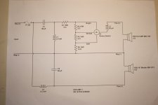
I am building an ESS AMT-1 type "clone" using a new Heil AMT and a new ESS 10" woofer. I want to duplicate the original AMT-1 crossover (see schematic attached), but I want to increase the crossover point from the original 800 Hz to 1100 Hz.
I could use available design software to make a Linkwitz-Riley 2nd order at 1100 Hz, but I want to use the original ESS design.
I have a LOT to learn about crossover design and function.
- I understand the 3 position switch/tweeter attenuation circuit, but what purpose does R1 and L3 serve in the original design?
-How would an L-pad be inserted into the original design to replace the three position switch attenuation circuit?
-Will the typical crossover design software values work for replacing C1, L1 and C2,L2 to raise the X-over freq to my desired 1100 Hz....and would the values of R1 and L3 also have to be changed at the same time.
Thanks to the group!!
Wayne
Attachments
Welcome to the forum!
R1 provides an initial, fixed degree of attenuation in the "Bright" position.
I'm not sure of the purpose of L3, but its value (0.083 mH) is very small, so its effect must be subtle (the experts will no doubt know wot's wot!)
If you are referring to using a variable L-pad control, you would remove all components to the right of L1 and connect the L-pad across L1 as shown in the attachment.
A simple crossover calculator won't do the job of reassigning the crossover frequency. What "available design crossover software" do you have access to?
Attachments
My old school knowledge tells me that to crossover at 1100 Hz instead of 800 Hz, all C and L values should be mutiplied by 0.73 - that should prompt the crossover design experts to respond to your query! 