

I can't see a need to replace the transformer for that reason. 69VAC total (assuming you are measuring both secondary windings in series) is well within a reasonable tolerance for the amplifier power supply and likely your mains power line voltage too. I wouldn't be too concerned about that 1.4% difference if measured with a typical DIY quality multimeter anyway.Whilst not a polymer breakdown .........my 405 transformer is putting out 69v so not good. I have this tx which fits in the case ok from a Yamaha amp 35v secondaries, could I use it to get the 405 up and running for a while?
Since the nominal secondary voltages of your Yamaha transformer match the Quad's, there's no reason you couldn't try it as an experiment, making certain you keep the 35VAC windings "in phase" so they add 35+35 VAC rather than cancel to zero and make odd noises. Assuming it has a lower VA rating than the original, you should check how much the DC rail voltages droop under load with a steady tone signal and a large dummy load before signing off on the job. It may not be big enough to deliver what you expect from a 405.
Last edited:
It is 69vac at each of the boards, it was a steady 50vac before..I can't see a need to replace the transformer for that reason. 69VAC total (assuming you are measuring both secondary windings in series) is well within a reasonable tolerance for the amplifier power supply and likely your mains power line voltage too. I wouldn't be too concerned about that 1.4% difference if measured with a typical DIY quality multimeter anyway.
Since the nominal secondary voltages of your Yamaha transformer match the Quad's, there's no reason you couldn't try it as an experiment, making certain you keep the 35VAC windings "in phase" so they add 35+35 VAC rather than cancel to zero and make odd noises. Assuming it has a lower VA rating than the original, you should check how much the DC rail voltages droop under load with a steady tone signal and a large dummy load before signing off on the job. It may not be big enough to deliver what you expect from a 405.
Try with another meter, on DC range.
Check the meter batteries as well, one of the reasons I keep analog meters around, they rarely give odd results.
Check wall supply voltage also.
Transformers do not change voltage so much.
Then see if any components have failed, for example Zeners and resistors in regulation circuit.
Check the meter batteries as well, one of the reasons I keep analog meters around, they rarely give odd results.
Check wall supply voltage also.
Transformers do not change voltage so much.
Then see if any components have failed, for example Zeners and resistors in regulation circuit.
Last edited:
There is no PSU regulation circuit in a Quad 405. Only a couple of stepdowns for the opamp.
Last edited:
So we can speculate on another reason for the high voltage.
50V DC will read 78.6164 V AC on a meter!
Wrong range?
🙄
50V DC will read 78.6164 V AC on a meter!
Wrong range?
🙄
Last edited:
My mistake, it is of course DC!It can't be AC at the boards. It has already been rectified and smoothed. Do you mean DC?
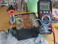
You measured exactly what, from what point to what other point, with what setting on your meter?
vcc+ and vee- meter setting as shown also across the capsYou measured exactly what, from what point to what other point, with what setting on your meter?
Attachments

So? No 69VDC there. But if you really do have it, there are two possible reasons: you have a shorted turn in the primary, or you have the voltage selector set wrong. The latter is very much more likely.
Last edited:
the pic was to show the setting of the meter and the voltage selector was removed some years backSo? No 69VDC there. But if you really do have it, there are two possible reasons: you have a shorted turn in the primary, or you have the voltage selector set wrong. The latter is very much more likely.

Still not too sure about your measurements,which vary from post to post.
Please confirm:
Do you read +70VDC and -70VDC at supply rails?
Specifically across terminals at 10000uF C13 and C14?
YES/NO/OTHER
please pick one.
Hint:
Please confirm:
Do you read +70VDC and -70VDC at supply rails?
Specifically across terminals at 10000uF C13 and C14?
YES/NO/OTHER
please pick one.
Hint:
You measured exactly what, from what point to what other point, with what setting on your meter?
You answered the second question, but not the first.vcc+ and vee- meter setting as shown also across the caps
The tx is out of the amp at the moment but this is it roughly connected up, I did connect a cap 22000uh 63v briefly and the meter showed 95v before the cap blewStill not too sure about your measurements,which vary from post to post.
Please confirm:
Do you read +70VDC and -70VDC at supply rails?
Specifically across terminals at 10000uF C13 and C14?
YES/NO/OTHER
please pick one.
Hint:
You answered the second question, but not the first.
Attachments
OUCH!!!!!!
There is some GROSS mismatch there, VERY DANGEROUS!!!
Such a big capacitor,can and will explode like a grenade, straight in your face.
You were lucky you didn´t get hurt.
At least I HOPE you didn´t. 😱
Clearly you connected it wrong: 70VAC into a bridge (which means rectified 100V peak) into a single 63V cap.
1) do not plug anything into Mains until this mystery is solved.
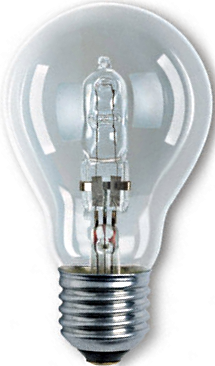
2) build a current limiting bulb setup,with a 40 to 60W tungsten filament bulb as limiter.
Real glowing wire inside a bulb type, no LED, CFL, etc.
You can still buy them as "high efficiency ones", an olive sized quartz halogen bulb inside a larger old style glass one.
Please draw what you built, plus a picture.
There is some GROSS mismatch there, VERY DANGEROUS!!!
Such a big capacitor,can and will explode like a grenade, straight in your face.
You were lucky you didn´t get hurt.
At least I HOPE you didn´t. 😱
Clearly you connected it wrong: 70VAC into a bridge (which means rectified 100V peak) into a single 63V cap.
1) do not plug anything into Mains until this mystery is solved.
2) build a current limiting bulb setup,with a 40 to 60W tungsten filament bulb as limiter.
Real glowing wire inside a bulb type, no LED, CFL, etc.
You can still buy them as "high efficiency ones", an olive sized quartz halogen bulb inside a larger old style glass one.
Please draw what you built, plus a picture.
Last edited:
- Home
- Amplifiers
- Solid State
- Incorrect secondary voltages on QUAD 405 transformer