My philosophy is the simpler is the better. You can get rid of the 2.2nF capacitors, as well. The next step will be to go for no-oversampling (removing the SAA7220), then rolling the opamps... This is a never-ending game.
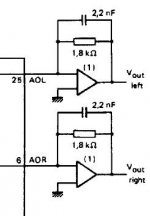
Don't forget the output of the opamp will be at DC so a blocking capacitor is needed. It is in the signal path, so...
Don't forget the output of the opamp will be at DC so a blocking capacitor is needed. It is in the signal path, so...
I plan on using LME49710 opamps instead of the OPA2604 shown.
Would sound quality improve if I just use one opamp per channel without the 2.2nF cap?
What is the second opamp on each channel for? Is this a low pass filter for rolling off the >20KHz digital rubbish? If so, I think I can live without it (I'm used to TDA1543 non-oversampling dacs without filtering).
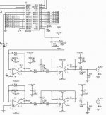
First opamp is the i/v converter, 2nd opamp is the lowpass filter.
Improve the power supply - separate the analog and digital 5v etc
Replace the clock with a better version
Use a tube i/v and output
Where do you stop??
Andy
Improve the power supply - separate the analog and digital 5v etc
Replace the clock with a better version
Use a tube i/v and output
Where do you stop??
Andy
My philosophy is the simpler is the better. You can get rid of the 2.2nF capacitors, as well. The next step will be to go for no-oversampling (removing the SAA7220), then rolling the opamps... This is a never-ending game.
Be careful! My first DAC was a TDA1541A, and I simply implemented that opamp circuit without the capacitors and it worked great. BUT, I was using a slow opamp, and when I upgraded to anything just reasonably faster, the sound would collapse after a few seconds, and the opamp would get too hot to touch
 . I reckon the opamp was forced into oscillation. I was really surprised it was that cap at first. I spent a lot of time reworking the power rail decoupling and grounding and stuff like that before I noticed the missing cap was the problem.
Also, I implemented NOS and it sounded awesome, but it sounded much better when I added an SAA7220P/B. But this was a DAC, not in situ, in a CD player, so my recloking was perhaps different.
Sorry, Oshifis, I very rarely disagree with you!
But, there's loads you can do 🙂
If you are doing any mods and component changes around the output OpAmps and filters than at the very least you have to do some simple measurement's to back up the changes, even if it's just a 20-20khz sweep from a test CD to make sure you havn't altered the response.
Have a read at http://www.diyaudio.com/forums/showthread.php?s=&threadid=92994&highlight=
Post #10 I actually measured the effects of this one.
Have a read at http://www.diyaudio.com/forums/showthread.php?s=&threadid=92994&highlight=
Post #10 I actually measured the effects of this one.
My inclination would be to drop the SAA7220 and low pass filter stage, to give a non-oversampling dac with active I/V (LME49710).
Any thoughts?
Any thoughts?
sharpi31 said:My inclination would be to drop the SAA7220 and low pass filter stage, to give a non-oversampling dac with active I/V (LME49710).
Any thoughts?
The schematic shown in post 4 does not use the SAA7220 and so is already NOS.
Andy
poynton said:
Improve the power supply - separate the analog and digital 5v etc
Replace the clock with a better version
Use a tube i/v and output
 Very true.
My little experience is that these three things give the most spectacular improvements. I would say in reverse order, I/V stage most important, then clock, PSU also very audible (especially, I think, on the Philips chipset).
Better, funnier, cheaper than fancy op-amps.
In my case, discrete "common-base transistor" I/V was the most spectacular upgrade. I preferred this to "passive I/V plus tube stage".
You'll find variants of the common-base I/V conversion here in the forums. Don't be intimidated by the difficulty of completely mastering how and why it works; if you are used to making your PCBs, the basic configurations are quite accessible and VERY effective.
I did these three modifications on a cheapo Marantz with TDA1541A, that now compares with, and beats my venerable Cambridge CD3.
And it was only "prototype mode": basic BJT common-base, Kwack clock, just separate transformer and 7805/7905/7915 for the DAC chip.
Have fun!
_
Phil, you are absolutely right. The datasheets of AD797 (Post #1) and OPA2604 (Post #4) are also mentioning a small capacitor. I never tried these opamps, but I found 68pF necessary for NE5534 to prevent oscillation and overshoot, same for OPA627 and none for OPA134 or THS4031. Proper bypassing is equally important.philpoole said:
Be careful! My first DAC was a TDA1541A, and I simply implemented that opamp circuit without the capacitors and it worked great. BUT, I was using a slow opamp, and when I upgraded to anything just reasonably faster, the sound would collapse after a few seconds, and the opamp would get too hot to touch
Tube IV. Really that much better than discrete?
I would've thought it would be different, but not markedly better - unless it was colouring the sound.
I would've thought it would be different, but not markedly better - unless it was colouring the sound.
Your scheme may be better
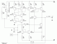
Here is the scheme.
may be think about non use the Digital Filter with TDA1541A
oe Use filete CXD2214S.
You must plus one thing which is image (scheme below)...
You need have a + polarisation, the Zero point is -2ma at TDA1541.
look here
Here is the scheme.
may be think about non use the Digital Filter with TDA1541A
oe Use filete CXD2214S.
You must plus one thing which is image (scheme below)...
You need have a + polarisation, the Zero point is -2ma at TDA1541.
look here
Attachments
op amps
I would leave two stage op amps in. Also I would use discrete op amps.
Don't waste your money buying someone else's already made op amps at extortion prices. There are plenty of diy discrete op amps ccts. on the net. Although high end op amps will outperform discrete op amps by a long shot, In my opinion sonicly the discrete op amps soften the sound and makes it more pleasant to listen to. This may be due to the lower performance figures (on paper that is) achieved by the discrete op amp. For me I whipped up four op amps and made two dual op amps at a cost of under $10.00 on vero board solder up on a high quality machined pin I.C. sockets. Then I installed The same sockets on the cd,s P.C.B and plugged them in. This way you can refer back to the
I.C. op amps and compare. It is dirt cheap and the cct. I found on the net uses only seven transistors and easy to build. They work pefectly in my Marantz cd-54 with the saa7030 removed.
Try it.
Regards
Billy D...
- Status
- Not open for further replies.
- Home
- Source & Line
- Digital Line Level
- Improvements to TDA1541 dac output stage?