Hello friends,
I have done this phono preamplifier, of Mr. Troels, which I am unsatisfied for its sound quality.
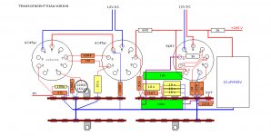
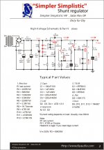
It is my first phono to valves and I am not an expert in this matter, I have made improvements but they are substantial, like Mr. Rod Colema's ht-hearte for heating, and PSU Mosfet HV Shunt Regs of SR. Salas.
Someone nice could tell me improvements that could be made ?, to improve its sound.
Regards
I have done this phono preamplifier, of Mr. Troels, which I am unsatisfied for its sound quality.
It is my first phono to valves and I am not an expert in this matter, I have made improvements but they are substantial, like Mr. Rod Colema's ht-hearte for heating, and PSU Mosfet HV Shunt Regs of SR. Salas.
Someone nice could tell me improvements that could be made ?, to improve its sound.
Regards
Attachments
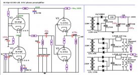
An SRPP like that realized with a 5751 is going to have very high output impedance, probably north of 15K ohm.. That whole stage ought to be redesigned with something else.
As I mentioned above, the psu is not that of the schematic is Simplistic Mosfet HV Shunt Regs, of S.R Salas, and the decoupling capacitors are Auricap of 1UF.
What improvements can be made with respect to the cathode resistors, higher or lower value?
What improvements can be made with respect to the cathode resistors, higher or lower value?
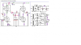
This is your scheme
what is so special about triode cascode? i´d put fet gyrator instead, needs just one tube.
output impedance will be smaller, and riaa could be recalculated to other values.
I'm thinking of replacing the 6c45p, for the 6n5p, the latter are double triode, so instead of 4 tubes would be in only 2 plus 2 12ax7, obviously the gain would be different.
With those very small cathode resistances the current and the repartition of the voltages over the two first triodes is problematical.
And the coupling capacitors rather small as the electrolytics in the power supply.
Mona
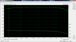
This is the measurement of the answer, after the modification that has advised me Ketje, It can be improved even more ?.
Thank you Ketje for your help has improved substantially
Attachments
In order to get 200volts on top of the first cascode the current in the 6k8 resistance has to be (255-200)/6k8=8mA.That's also the current in the triodes and that depends on the 60R4 cathode resistor.But not very reliable, so experiment with the cathode resistor to get 200volt on top.
For the second stage, with 12AX7, the 3k are better replaced with 1k2 to get more output drive.
Mona
For the second stage, with 12AX7, the 3k are better replaced with 1k2 to get more output drive.
Mona
In order to get 200volts on top of the first cascode the current in the 6k8 resistance has to be (255-200)/6k8=8mA.That's also the current in the triodes and that depends on the 60R4 cathode resistor.But not very reliable, so experiment with the cathode resistor to get 200volt on top.
For the second stage, with 12AX7, the 3k are better replaced with 1k2 to get more output drive.
Mona
Thanks Ketje, I will try it and comment the results.
Regards.
.In order to get 200volts on top of the first cascode the current in the 6k8 resistance has to be (255-200)/6k8=8mA.That's also the current in the triodes and that depends on the 60R4 cathode resistor.But not very reliable, so experiment with the cathode resistor to get 200volt on top.
For the second stage, with 12AX7, the 3k are better replaced with 1k2 to get more output drive.
Mona
I have made the modifications but I have not had positive results, in reference to the sound quality.
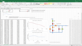
I have found an excel here in the forum of our friend rjm, for the calculation of the equalization riaa, it is possible to say that I have put the components of my phono stage and it is not good.
Attachments

.
I have made the modifications but I have not had positive results, in reference to the sound quality.
I have found an excel here in the forum of our friend rjm, for the calculation of the equalization riaa, it is possible to say that I have put the components of my phono stage and it is not good.
Here is a modification made by me.
Is this modification correct? Or is it not reliable?
Attachments
The mod's i sugested where intended to get more headroom and output drive to prevent signal top cutting with strong signals, not to change the frequency response.
The correction network was ok.
What you do now is another way of making the filter, if well dimensioned, same result.
The Rout from the first stage is somewhat less than the 6k8 anode resistor, take 6k.
The Rin is the grid resistor of the next stage, 1M.
Resulting , with the same capacitors Ca=10n and Cb=100n, in Ra=67k and Rb=10k5.
Mona
The mod's i sugested where intended to get more headroom and output drive to prevent signal top cutting with strong signals, not to change the frequency response.
The correction network was ok.
What you do now is another way of making the filter, if well dimensioned, same result.
The Rout from the first stage is somewhat less than the 6k8 anode resistor, take 6k.
The Rin is the grid resistor of the next stage, 1M.
Resulting , with the same capacitors Ca=10n and Cb=100n, in Ra=67k and Rb=10k5.
Mona
Ketje thank you very much for your help, if I understand correctly, is correct modification that have attached in the scheme?
Attachments
No, it's not the circuit used by the calculator.And hence the values aren't correct.
Mona
Thanks Ketja, but as I am very clumsy, could you tell me the modifications in the original scheme? do not really understand
Attachments

- Home
- Amplifiers
- Tubes / Valves
- Improvements in this riaa tube