Hi guys,
I've been working on a direct drive amp for ESLs for several years now, on and off, and need to ask a basic but important question.
If you design an amp for flat freq response, and knowing that the ESL is a cap load, your current requirements at 20kHz can be pretty enormous (100's of mA to 0.5A) at a few kV. Not a simple design task.
But in my understanding, the efficiency (if that is the right term here) of an ESL also increases with frequency. That would suggest that to get a flat acoustic response your driving amp can get away with an output that drops with frequency.
Is this a valid reasoning? How does the directivity figure in this?
Thanks for any pointers.
Jan
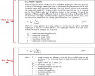
For unsegmented ESLs, where the directivity is a fall-out of the physical size and shape of the panel, the required voltage and current for flat on-axis response is contained in the Walker equations for point source and line source ESLs.
Flat response for an unsegmented Point-Source ESL requires:
- Voltage falling -6dB/oct with increasing frequency
- Constant current
Flat response for an unsegmented Line-Source ESL requires:
- Voltage falling -3dB/oct with increasing frequency
- Current increasing +3dB/oct with increasing frequency
The Walker equations assume flat panels with mass-less diaphragms. If diaphragms thicker than a few microns are used, or the panels are physically curved to improve HF dispersion, voltage and current will need to be increased with frequency relative to the Walker equations to retain a flat on-axis response.
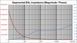
The popular segmented line source ESLs that use resistor ladder networks provide improved dispersion and an easier load. Constant voltage drive produces a flat SPL response. The example plots shown for a 10 segment line source ESL shows the capacitive load drop from a flat 1350pF(for an unsegmented ESL) to a more manageable 200pF in the upper octave. Note also that the phase of the impedance for these segmented line sources is roughly -45deg rather than -90deg of a pure capacitance.
Hopefully this brief summary will provide enough info to help you better quantify the voltage/current requirements for your amplifier.
Flat response for an unsegmented Point-Source ESL requires:
- Voltage falling -6dB/oct with increasing frequency
- Constant current
Flat response for an unsegmented Line-Source ESL requires:
- Voltage falling -3dB/oct with increasing frequency
- Current increasing +3dB/oct with increasing frequency
The Walker equations assume flat panels with mass-less diaphragms. If diaphragms thicker than a few microns are used, or the panels are physically curved to improve HF dispersion, voltage and current will need to be increased with frequency relative to the Walker equations to retain a flat on-axis response.
The popular segmented line source ESLs that use resistor ladder networks provide improved dispersion and an easier load. Constant voltage drive produces a flat SPL response. The example plots shown for a 10 segment line source ESL shows the capacitive load drop from a flat 1350pF(for an unsegmented ESL) to a more manageable 200pF in the upper octave. Note also that the phase of the impedance for these segmented line sources is roughly -45deg rather than -90deg of a pure capacitance.
Hopefully this brief summary will provide enough info to help you better quantify the voltage/current requirements for your amplifier.
Attachments

Steve, thanks for this, exactly what I was looking for. I think what I should do is construct a segmented line source model to use as a load in LTspice.
Right now my amp can drive 1000pF @ 10kHz full level. With the fall-off of drive, or the fall-off of load capacitance, that should be sufficient for most cases.
Back to the drawing board ;-)
Jan
Right now my amp can drive 1000pF @ 10kHz full level. With the fall-off of drive, or the fall-off of load capacitance, that should be sufficient for most cases.
Back to the drawing board ;-)
Jan
The DD amp I used for a few decades (B+ of 2300v) essentially drove a bank of wire wound resistors in parallel with the ESL panels. The load was pretty much just resistive which makes designing the amp a whole lot simpler.
B.
B.
But the power dissipated in those resistors probably was a lot more than in the panels?
Yes, I am sure it was a lot more. ESLs are efficient and 1 acoustic watt will destroy your hearing; so the actual power needed to drive an ESL panel is just a few watts. (But when you drive an ESL through a step-up transformer from the familiar audio amp, you need lots of volts. To get lots of volts from the usual 4-Ohm audio amp means dozens or even hundreds of watts must be available from the amp to go into your transformer on peaks.)
Wasting a few watts in the resistors is hardly anything to fret about. Amps just love resistors as a load and don't like capacitors as a load.
B.
Last edited:
What bolserst wrote for the non-line-source case applies in the far field, and to be in the far field, the distance between loudspeaker and listener has to be much greater than the wavelength divided by two pi for the lowest frequency of interest, and greater than the diagonal of the part that radiates treble squared divided by the wavelength of the highest frequency of interest. That last requirement is almost never met for unsegmented ESLs.
In any case, Walker's equation also applies to the vector sum of the currents through the segments in a segmented flat-panel ESL, so that sum has to be made frequency-independent one way or other to get a flat far-field response. Two examples are QUAD's damped transmission line trick and the crossover filter of Frank Verwaal, which both make the ESL behave resistive above a certain frequency. An ESL that is capacitive and meant to be driven by a frequency-independent voltage is either a headphone or poorly designed.
In any case, Walker's equation also applies to the vector sum of the currents through the segments in a segmented flat-panel ESL, so that sum has to be made frequency-independent one way or other to get a flat far-field response. Two examples are QUAD's damped transmission line trick and the crossover filter of Frank Verwaal, which both make the ESL behave resistive above a certain frequency. An ESL that is capacitive and meant to be driven by a frequency-independent voltage is either a headphone or poorly designed.
While studying the literature I decided to measure the impedance of my ML Aerius speakers.
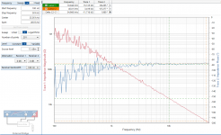
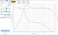
First up is the transfer function from the input (no woofer, only the ESL section) with 1000pF load and with the actual panel load (not biased). Almost the same, some deviation at higher frequencies.
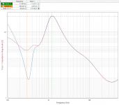
The second is the input impedance as seen by the driving amp. This is without the woofer, if that was connected the result would have been lower.
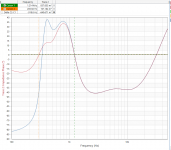
Lastly, the panel only, impedance versus frequency, showing pretty much a pure capacitance. Calculation from the impedance point at 10kHz gives 1030pF. This is panel-to-panel.
From the transfer function, assuming the acoustic output would be fairly flat, I would conclude this is a voltage drive speaker, correct?
Jan
First up is the transfer function from the input (no woofer, only the ESL section) with 1000pF load and with the actual panel load (not biased). Almost the same, some deviation at higher frequencies.
The second is the input impedance as seen by the driving amp. This is without the woofer, if that was connected the result would have been lower.
Lastly, the panel only, impedance versus frequency, showing pretty much a pure capacitance. Calculation from the impedance point at 10kHz gives 1030pF. This is panel-to-panel.
From the transfer function, assuming the acoustic output would be fairly flat, I would conclude this is a voltage drive speaker, correct?
Jan
Attachments
Last edited:
Apparently. It is probably either curved, or using a fairly thick diaphragm, or not meant to be listened to in the far field.
…From the transfer function, assuming the acoustic output would be fairly flat, I would conclude this is a voltage drive speaker, correct?
The Aerius is a finite length line source with a curved panel. To achieve a flat response required a careful balancing of acoustic and electrical equalization. For flat response, an ESL line source with a flat panel needs a voltage drive that falls -3dB/oct with increasing frequency. The 30deg curve of the 8” wide panel droops the on-axis response by roughly -3dB/oct starting at about 2kHz. So above 2kHz, a flat voltage drive will result in roughly flat response. Below 2kHz, the voltage would need to retain the 3dB slope down to crossover…if the line source was tall. But, it is only 38” in height. So, at typical listening distance of 9ft, the ESL starts to behave like a point source below 1khz(this transition frequency changes with distance). The voltage required for flat response needs to transition from 3dB to 6dB slope to compensate. Note that with a finite length line source, this compensation only works perfectly for one listening distance.
See comments posted on the compromise Martin Logan uses when designing their equalization:
About to take the ESL plunge
Break-point for transition from line-source to point-source discussed here:
Segmented Wire Stator ESL simulator (esl_seg_ui)
Attachments
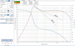
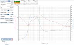
As much as I hate to admit, Paul was right: with the woofer connected, through it's own xover, the imput impedance of the combination now stays above 5R. Without the woofer it dipped below 2R.
See attached graphs, blue without woofer (I used an 8R resistor as 'woofer' for the measurements).
Jan
See attached graphs, blue without woofer (I used an 8R resistor as 'woofer' for the measurements).
Jan
Attachments
- Home
- Loudspeakers
- Planars & Exotics
- Impedance vs. frequency of ESL vs freq response