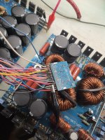
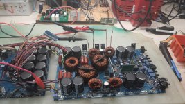
Goodmorning everyone ! I have the impact xt 10kw amplifier under repair! I have no damaged mosfet but as soon as I try to give the 12v the amplifier turns on and then turns off after about 3 seconds! does anyone know anything about it or can you find the pattern somehow?
Attachments
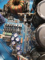
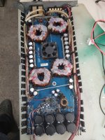
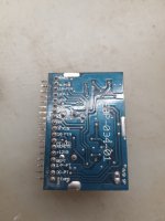
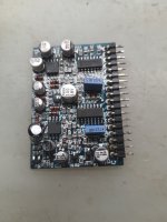
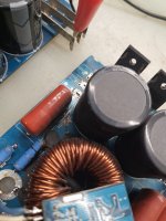
hello Perry! I did a test with the pwm card! I tried the pwm card on a test bench and I saw that putting the protection pins on gnd I have the square wave output! from the diagram and checking with the tester I saw that the driver board of the DLM4000A amplifiers has a pin that goes to the PWM board! is it possible that the driver board of the finals is damaged? Do you have some advice ?As soon as the pwm started, the relay tripped and the voltage that goes to the final stage is about 240v!
Attachments
Where were your probes (exact points in circuit) when you measured 240v?
What's the DC voltage measured directly across the speaker terminals?
What's the DC voltage measured directly across the speaker terminals?
Are you saying that you measured across both rails or did you measure across a single rail cap?
What's the DC voltage measured directly across the speaker terminals?
What's the DC voltage measured directly across the speaker terminals?
I didn't mention it earlier but it's not a good idea to blindly ground points unless you know precisely what's driving the circuit. In many instances, grounding can cause damage to the driver which can lead to more, troubleshooting/problems.
What happens if you disconnect the wires from the terminals that are shorted together?
What happens if you disconnect the wires from the terminals that are shorted together?
Perry I unplugged the output card to see if the problem was suv that card and to check if the pwm card started !

the resistor carries the current to the buffer transistors of the pwm! so now the power is working but I still have the problem that as soon as I turn it on it turns off after 2 seconds! I tried to remove the output mosfet drive card but I have the same problem! Now I try to disassemble the output mosfets! I noticed that as soon as I turn on the woofer output I have -10v
Are you saying that with both the output FETs and the driver board out of the amp that you have 10v across the output terminals?
If so, if you touch a speaker or dummy load across the output terminals, does the voltage drop to 0v or does that cause the amp to draw increased current?
If so, if you touch a speaker or dummy load across the output terminals, does the voltage drop to 0v or does that cause the amp to draw increased current?

You should install at least one per bank and the driver board to see if it will power up. You'll have to very carefully monitor the temperature of all heatsink mounted components to ensure that none overheat.
For the amp to be as reliable as possible, you'll have to replace all in the bank with the failed output with FETs from a common production batch.
For the amp to be as reliable as possible, you'll have to replace all in the bank with the failed output with FETs from a common production batch.
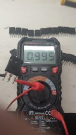
When you posted the meter readings showing the bad FET, the meter was on diode-check. You need to check all of the FETs with the meter on ohms. You should get a resistance between the gate and the other two terminals that's the same as when the meter's probes are not touching anything.
Did you confirm that all gate resistors were within tolerance.
Did you try touching the load to the terminals when the outputs were out of the board to see if the 10v drained off?
Did you confirm that all gate resistors were within tolerance.
Did you try touching the load to the terminals when the outputs were out of the board to see if the 10v drained off?
- Home
- General Interest
- Car Audio
- Impact XT 10K