I made a tda2030 subwoofer 2.1 amp, but at first everything seemed to move on well, but as time went, i started smelling burning smoke from my surround speakers, i disconnected them, and when i tested with a multimeter, i got 19vdc at the outputs, am using 14vac dual transformer, yet if i switch the whole set up on, the sub speaker working normally, so please help me
can you post the circuit diagram of your amplifier?
does it have a split supply?
if not: do the amps have output capacitors?
also note that you should post in the "solid state" forum, "new diyAudio platform Q&A" is only related to forum platform related questions!
(i will ask moderators to do it - edit: thanks mooly, of course "chip amps" is the correct forum!)
Last edited:
 Moved to Chip Amps.
But i ignored the IN4001 diodescan you post the circuit diagram of your amplifier?
does it have a split supply?
if not: do the amps have output capacitors?
also note that you should post in the "solid state" forum, "new diyAudio platform Q&A" is only related to forum platform related questions!
(i will ask moderators to do it - edit: thanks mooly, of course "chip amps" is the correct forum!)
Attachments
I neve
can you post the circuit diagram of your amplifier?
does it have a split supply?
if not: do the amps have output capacitors?
also note that you should post in the "solid state" forum, "new diyAudio platform Q&A" is only related to forum platform related questions!
(i will ask moderators to do it - edit: thanks mooly, of course "chip amps" is the correct forum!)
I dont have the output caps..can you post the circuit diagram of your amplifier?
does it have a split supply?
if not: do the amps have output capacitors?
also note that you should post in the "solid state" forum, "new diyAudio platform Q&A" is only related to forum platform related questions!
(i will ask moderators to do it - edit: thanks mooly, of course "chip amps" is the correct forum!)
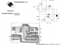
that schematic is exceptionally bad.But i ignored the IN4001 diodes
you should use the official data-sheet circuit:
https://www.alldatasheet.com/datasheet-pdf/pdf/25044/STMICROELECTRONICS/TDA2030A.html
you will find the single supply circuit on page 1 and 4 and the split supply schematic on page 2 and 7.
I had the same problem several months ago with my amp. The capacitor (22uF) at inverting input was directly shorted: 2ohm across it measured once taken off the PCB.
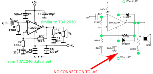
and this is what I am talking about:
green = corrections to the schematic
red = probable error due to bad schematic (negative speaker connection must NOT be connected to -VS but to ground!)
green = corrections to the schematic
red = probable error due to bad schematic (negative speaker connection must NOT be connected to -VS but to ground!)
Attachments
Last edited:
This measure is respect to ground or to supply negative?. Is the input AC coupled to previous stage?
Yes sir it isThis measure is respect to ground or to supply negative?. Is the input AC coupled to previous stage?
Yeah sir, i did connect it to the ground..and this is what I am talking about:
green = corrections to the schematic
red = probable error due to bad schematic (negative speaker connection must NOT be connected to -VS but to ground!)
do you get the same DC at both stereo outputs? (I suppose you have stereo outputs, as it is a 2.1. amp)
do you get the same DC at both stereo outputs? (I suppose you have stereo outputs, as it is a 2.1. amp)
There is error in that circuit, never use it.But i ignored the IN4001 diodes
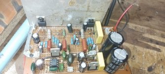
Yeah its a stereo.. i had to use two ics for the sub output, then two for the surrounds, so i ignored one ic for the sub output, and left one ic that is marked with red in the pic attached below, then the yellow markings show where the ics for the surrounds have to be, i removed them due to burning ny speakers, and i have been even interchanging the positions of those ics but the same... may a defective ic also be a result of such behaviour? But the sub is working normally, no hum, good bass but the sorrounds
Attachments


Yeah its a stereo.. i had to use two ics for the sub output, then two for the surrounds, so i ignored one ic for the sub output, and left one ic that is marked with red in the pic attached below, then the yellow markings show where the ics for the surrounds have to be, i removed them due to burning ny speakers, and i have been even interchanging the positions of those ics but the same... may a defective ic also be a result of such behaviour? But the sub is working normally, no hum, good bass but the sorrounds
Okay mr thanksThere is error in that circuit, never use it.
i suppose this is a bad idea, as the sub may be a BTL amp.so i ignored one ic for the sub output,
did you follow a complete 2.1 schematic?
can you post it?
of course the ICs can be defective...
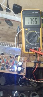
as i see in your picture you measured -19 V at the output (because leads seem to be exchanged?).
so it seems you get -Vs at the speaker output.
(edited) or you have +Vs at the speaker ground.
Last edited:
i suppose this is a bad idea, as the sub may be a BTL amp.
did you follow a complete 2.1 schematic?
can you post it?
of course the ICs can be defective...
as i see in your picture you measured -19 V at the output (because leads seem to be exchanged?).
so it seems you get -VC at the speaker output.
I am surmising , because you stated '14vac dual transformer' that you have +19V / 0V / -19V power (after rectification & smoothing).
The ground/chassis symbol that appears several times on the on the schematic - these points are all connected to the 0V of the power supply.
The ground/chassis symbol that appears several times on the on the schematic - these points are all connected to the 0V of the power supply.
- Home
- Amplifiers
- Chip Amps
- I'm having 19vdc at my surround speaker outputs, yet the subwoofer output is okay, my speakers even got burnt.