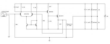
I designed this to drive my in-ear monitors. They only need about 1/4 of a volt into 27 Ohms, because the 'phones are so sensitive. I thought it was a good excuse to go class A 🙂 It's going to be powered by 4 x AA batteries. 
It uses stuff I have already lying around. I breadboarded it tonight and it worked fine out to 160Khz. ( Driving a 33Ohm resistor with 2v p-p)
Gonna build it properly tomorrow. Anything I should be worried about, or does it look ok at first glance?
Thanks in advance!
It uses stuff I have already lying around. I breadboarded it tonight and it worked fine out to 160Khz. ( Driving a 33Ohm resistor with 2v p-p)
Gonna build it properly tomorrow. Anything I should be worried about, or does it look ok at first glance?
Thanks in advance!
Attachments
Hi Wildswan,
what DC did you measure at the output? 6V across 27Ohm would dump 220mA into your IEMs, which are not built to dissipate 1.3W...
what DC did you measure at the output? 6V across 27Ohm would dump 220mA into your IEMs, which are not built to dissipate 1.3W...
batteries are not constant V sources, as they dischrage the V will drop - to less than 1 V per cell
your circuit will not split the tail current evenly in the diff pair as supply V varies - mismatched diff pair current gives distortion
puting a mirror in the diff pair collectors (and using a R for the tail current if you want to play some min transistor count game) should give lower distortion over operating V supply range
another entry in the 5 transistor low distortion, low V amp game:
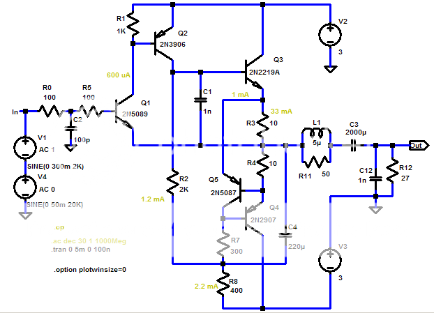
Q1-3 are a cf tripple, Q4,5 are a "normal" feedback constant current source in an unusual orientation: R3,4 set the 30 mA bias current, since the output is taken from the middle of the sense resistors the output is push-pull Class A up to +/-60 mA
C4 AC bootstraps the bias resistors
C1 shunting Q3 BE compensates the tripple (at least in sim)
2nd -113 dB, 3rd -133 dB @ .25 Vrms 2KHz
your circuit will not split the tail current evenly in the diff pair as supply V varies - mismatched diff pair current gives distortion
puting a mirror in the diff pair collectors (and using a R for the tail current if you want to play some min transistor count game) should give lower distortion over operating V supply range
another entry in the 5 transistor low distortion, low V amp game:
Q1-3 are a cf tripple, Q4,5 are a "normal" feedback constant current source in an unusual orientation: R3,4 set the 30 mA bias current, since the output is taken from the middle of the sense resistors the output is push-pull Class A up to +/-60 mA
C4 AC bootstraps the bias resistors
C1 shunting Q3 BE compensates the tripple (at least in sim)
2nd -113 dB, 3rd -133 dB @ .25 Vrms 2KHz
Attachments
Hi sek,
I measured about 15mV offset at the output. I didn't match anything when breadboarding it, so I'm hoping I can reduce it in the final design.
I might have to put in a pot somewhere to adjust offset voltage. ( Either in the FB path or the differential amp tail...)
You make a good point about the 6v thing. Some protection circuit would certainly be in order! (I really like my IEMs😀 )
Cheers!
Hi,
I think the TLE2426 would be a good idea to balance the supply rails without wasting battery current, but it's not easy to source everywhere.
JCX's specifications sound like a dream, though! 😉
But as 60mA is by far enough to drive the headphone and you use a coupling cap anyway, why make it push-pull at all?
Another approach would be to use a simplified class A circuit and make it three channels, the third buffering the ground return from the headphones. If you match the semiconductors for equal DC offset, the ground channel DC offset (of same value and polarity) cancels out the DC of the left and right channels (thermal coupling provided). Has been tried with modified Szekeres or Zen like class A amp projects, although not by myself... 😉
Wildswan, which IEMs do you use, btw?
Cheers.
- Status
- Not open for further replies.