I am currently trying to design a stepped attenuator for a generator.
I want it to have a constant impedance, both for the input and the output, to be as simple as practical, to have the ability to go to 0dB and to use a single circuit selector.
This is how far I arrived:

Only 5 sections are drawn, the subsequent sections being very similar.
I have the feeling that it would be possible to streamline it further, but I cannot find useful info on the net.
Does someone have a brighter idea?
I want it to have a constant impedance, both for the input and the output, to be as simple as practical, to have the ability to go to 0dB and to use a single circuit selector.
This is how far I arrived:
Only 5 sections are drawn, the subsequent sections being very similar.
I have the feeling that it would be possible to streamline it further, but I cannot find useful info on the net.
Does someone have a brighter idea?
While this is an interesting challenge maybe just buying an off the shelf makes more sense. There is a lot of technique making one with extended bandwidth. Especially for larger loss steps. This is what I would get: https://www.ebay.com/itm/2764532993...x2XQKLDVifAov23Md/viqpNJaV|tkp:Bk9SR5SC6_KNZA
There is a lot of relevant info here: https://www.technicalaudio.com/pdf/Daven/Daven_Catalog_1967.pdf Making one from scratch means finding odd resistor values and working out how much parasitics will compromise the performance. Tech Labs told me they would take a file to resistors to adjust them. And terminated vs. unterminated will be a source for errors. If RF you then also need to make sure the resistors are still resistors at the highest frequency of interest.
Thanks, interesting contribution as usual, and in fact I have ready-made attenuators fitting the bill, except that the power handling is too marginal. 1 or 2W doesn't seem like much, but for integrated thin or thick film resistor networks, it is a big ask.
I could certainly find a suitable model for a non-negligible price, but in fact I need a number of them: two decades, 1dB steps and 10dB.
Odd resistors values are no problem for me, and the bandwidth is not a problem either: video frequencies at most, and I have enough experience to handle much more than that.
I have the gut feeling that the draft I posted could be significantly simplified/improved, but at the moment I do not see how.
Maybe I have to sleep one or two nights on it to see the light...
And I found this reall complete documentation on attenuators. http://ael.chungbuk.ac.kr/lectures/graduate/고급전자기학2/주별교안/resistive-attenuator.doc It covers everything. I don't think you can make your circuit much simpler. However there are ways to make it much more complex. . .
Maybe an idea...
I've been designing attenuators for guitar amplifiers. Ignoring reactive parts, the way they work is as a series of switched stages, each twice the dB reduction of the previous. The basis of each stage is that with a basic T or Pi arrangement, you can determine values to achieve whatever dB and impedances in or out are required. There's a limit where one resistor of the three in each stage gets to zero ohms, and this sets the minimum attenuation. I just have three stages, -3.5, -7 and -14dB, and with them I get 8 equal steps of -3.5dB, depending which are switched on and off.
But with say 7:switched stages, each with 3 resistors, you could get 2^7 steps, and so could have 128 equal dB steps, each with equal impedance in and out?
Binary-sequenced attenuators are well-known, but I am looking for a topology using a single 1 among n selector (single deck), and having a constant input and output impedance; a big ask
Use that single deck to switch a diode array that selects the appropriate relays for a binary-sequenced attenuator.
Yes, that's an option I considered, but it means a lot of additional hardware. In the end, I opted for a compensated resistive divider for the first, 1dB stage and a double deck switch for the subsequent 10dB steps.
The input of the first stage is not really impedance-constant (but it doesn't matter too much), but its output is, and the 10dB stage is completely consistent for both the input and output.
Thus, a tradeoff: one additional deck, but it remains acceptable (for me anyway)
The input of the first stage is not really impedance-constant (but it doesn't matter too much), but its output is, and the 10dB stage is completely consistent for both the input and output.
Thus, a tradeoff: one additional deck, but it remains acceptable (for me anyway)
Inspired by the Amber 3501. It can be used as a balanced attenuator or two independent single-ended ones.
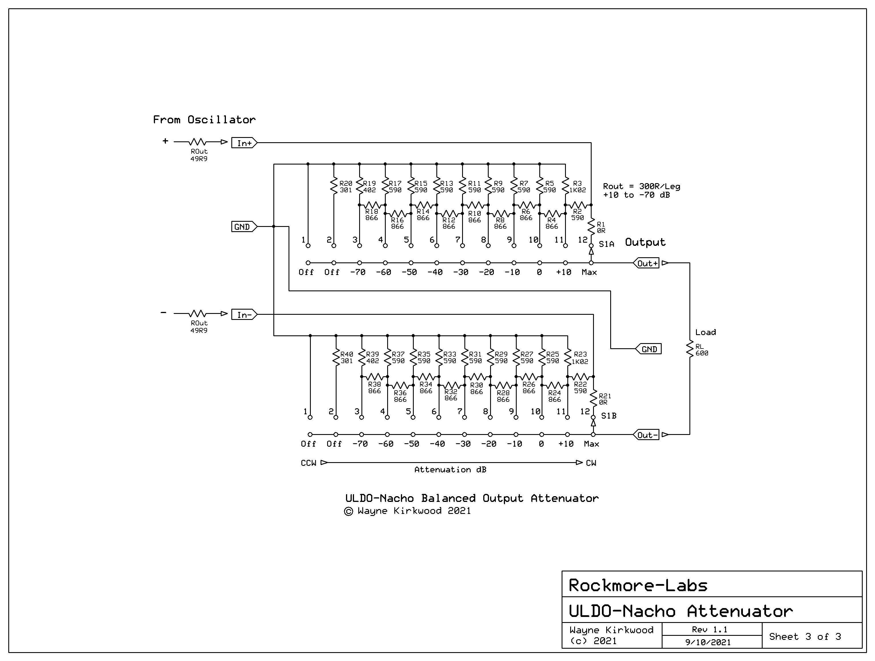
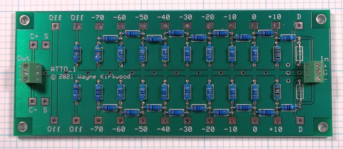
https://ka-electronics.com/shop/index.php?route=product/product&path=67&product_id=114
https://ka-electronics.com/shop/index.php?route=product/product&path=67&product_id=114
- Home
- Design & Build
- Equipment & Tools
- Ideas for a stepped attenuator?