I believe this was drawn up in some sort of CAD program and whoever did the drawing saw the right shape on screen but didn't check the orientation.
I've done this sort of thing many times in my own board designs, but it's not something I'd have thought would get through QC at a company as big as TE Connectivity and I'd also have thought that somebody before me would have said something to Digikey.
So, I might well be wrong, which is why I'm asking you to take a look and say if you see anything amiss.
Thanks
Attachments
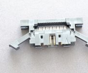
Looks fine to me. The section with the gold pins would be pushed onto the cable in a vice or similar, then the arms serve to eject an IDC plug from this socket. Most IDC sockets are board mount, this is a less often seen panel mount with ribbon version.
"Looks fine to me. . . ."
I thought so too until the first one I tried to use shattered under applied pressure without moving a micron toward closing down on the ribbon, prompting another more careful look.
My experience has always been that passive mechanical latches wedge into place and close with at least a 90º shelf to prevent movement in the direction of release. These ones (2 on each side for 4 in all) look to me to be reversed. They certainly prevent closure.
While I'd love to hear from tech support that there's a new way of doing things with instructions given for its implementation , nine days after submitting my questions together with photos it's radio silence from both companies.
I'd have thought it easy enough to send somebody to pull one off the shelf and see if they can make it work. Apparently not.
Attachments

I use a sacrificial plug to apply pressure to these sockets, that applies pressure direct to the base of the pins.
Do you have the strain reliefs in correctly? Aren’t they supposed to be up more? I use these a lot but the female type and with an FCI ‘Quickie’ and have to say I’ve never had a problem. I use a vice and a thin piece of wood - the assembly tools are prohibitively expensive.
I’ve used the 3M version before which has the option of using the ejectors that stay with some pins.
I recall the ejectors work with the mating socket having the strain relief added, sorry its was many years ago.
I recall the ejectors work with the mating socket having the strain relief added, sorry its was many years ago.
Thanks fellows for responding.
When doing the design I already had ribbon in pre-terminated lengths and simply needed a panel mount receptacle to take them. Digikey only had two possibilities at the time. The ribbon carries 350V and so this one's retaining arms made the decision for me.
I haven't had the chance to do anything with them other than attempt to close one down on a short length of ribbon to test the assembly. As the first one broke and the price has nearly doubled since I bought them years ago , I'm not keen to do any more experiments without first figuring out if there is some special technique for putting them together that I need to learn. Hence my attempt to get info from TE and Digikey.
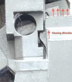
I"m posting a closer view of the feature that poses the problem. The triangular catches are molded surface features of the plastic body not the type mounted on hidden spring arms. They have no give and they very effectively prevent any movement to clamp down on the ribbon.
I may well be wrong but all past experience with such latching assemblies makes me think the catches should be sloping in the opposite direction from their present orientation so that the point of the ramp can wedge open the base , allowing it to move down onto the ribbon. (I hope my wording makes sense) .
I doubt myself only because TE is such a big company and surely they would have picked up on a mistake like this if it were one. However if it is as intended , there is no way to close it without some special method , of which there is no instruction available that I have been able to find.
Since I bought them years ago, their price has nearly doubled , so I 'm not particularly keen on breaking a few more in order to figure them out.
I'd thought of simply trimming off the catches and gluing the assembly closed, but as the ribbon has to carry 350V , a solid mechanical lock is really what I want.
Thanks
When doing the design I already had ribbon in pre-terminated lengths and simply needed a panel mount receptacle to take them. Digikey only had two possibilities at the time. The ribbon carries 350V and so this one's retaining arms made the decision for me.
I haven't had the chance to do anything with them other than attempt to close one down on a short length of ribbon to test the assembly. As the first one broke and the price has nearly doubled since I bought them years ago , I'm not keen to do any more experiments without first figuring out if there is some special technique for putting them together that I need to learn. Hence my attempt to get info from TE and Digikey.
I"m posting a closer view of the feature that poses the problem. The triangular catches are molded surface features of the plastic body not the type mounted on hidden spring arms. They have no give and they very effectively prevent any movement to clamp down on the ribbon.
I may well be wrong but all past experience with such latching assemblies makes me think the catches should be sloping in the opposite direction from their present orientation so that the point of the ramp can wedge open the base , allowing it to move down onto the ribbon. (I hope my wording makes sense) .
I doubt myself only because TE is such a big company and surely they would have picked up on a mistake like this if it were one. However if it is as intended , there is no way to close it without some special method , of which there is no instruction available that I have been able to find.
Since I bought them years ago, their price has nearly doubled , so I 'm not particularly keen on breaking a few more in order to figure them out.
I'd thought of simply trimming off the catches and gluing the assembly closed, but as the ribbon has to carry 350V , a solid mechanical lock is really what I want.
Thanks
Attachments
I'd be a bit worried with 350V on a ribbon cable - especially at the cut end of the ribbon. They are often rated less than 350V overall, let alone with cut ends. Perhaps consider encapsulating the ribbon ends after cutting?
Hi Mark,
Thanks for warning me . In this case though I'm using ribbon which has been hi-pot tested at 2KV so not worried there. I don't think the wire will be the concern but the connector pins if anything . That's why I'm using 16 conductor cable so that I can leave some positions unused as spacers between.
Everything is on hold though until I hear back from Digikey or TE about the connector. Not sure if you saw the detail I posted in post #7 above but I just can't see it as anything but wrong.
- Home
- Design & Build
- Parts
- IDC connector, Visual Inspection