
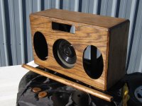
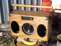
I'm posting this in subwoofers because the bass portion (and the crossover to the rest) is the only part I really designed and have questions about, at least so far. This project isn't particularly reproduceable because I used random pulled drivers from cars, though the bass section was designed to be replaced by a dayton driver if/when it fails.
Parts:
-Mids and tweets are self-contained 4ohm 'premium sound' speakers I pulled from a car, and presumeably have their own crossover inside.
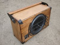
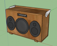
-Bass driver is an unlabeled 2ohm+2ohm dvc 8" pancake driver I also pulled from a different car. Should be replaceable with a front mounted DS215-88, though it would need a different grill
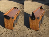
-Passive radiator is a Dayton DS315-PR
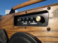
-Amp is the same 2.1 bluetooth model found in the Blast Box and Executive kits
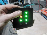
-Batteries and charger board are the big ones from parts express (5x26650s)
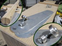
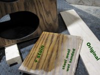
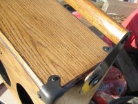
The design is intended to be used outside away from any boundaries. Cones of the woofer and passive radiator were enamel painted and polyurethane coated.
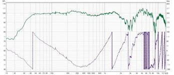
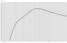
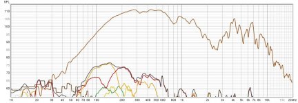
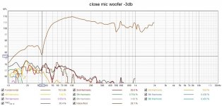
I expected much more of a underdamped/boombox style tuning, with a peak around 70-80hz and a droop extending below that, going by HornResp and WinISD. I figured that would at least make it 'loud' at the expense of flat response. 1m outdoor measurements (not completely away from reflections, but away from the corner of the nearest building at least) suggest that I ended up more of a hifi tuning, with flat response down to 50hz and a steep rolloff below that. I am completely happy with that, both in theory and in how it sounds, I'm just a bit baffled as to how I got there. FWIW I didn't measure with different amounts or no weight on the passive radiator as I was too happy with the response I got.
My main question is; my understanding of crossovers is largely amateur (matching levels), but I hear phase is just as important. Did I just stumble upon an ideal 150hz crossover, given the controls I have and the drivers I'm using? 150hz 1st order HP, lowpass is wide open so ~150hz 2nd order, gain shown down a little on the mid/tweets, as well as maxed out (unhelpfully labelled 'flat'). This appears to have a very smooth phase line all the way through the crossover region, but I don't know if that is what I should be looking at.

Attachments
-
 1.jpg559.9 KB · Views: 216
 -
 3.jpg746.9 KB · Views: 154
 -
 4.jpg662.9 KB · Views: 156
 -
 2.jpg533.2 KB · Views: 174
 -
 3d model.PNG38.5 KB · Views: 151
 -
 sp phase flat.jpg162.8 KB · Views: 133
 -
 distortion.jpg137.8 KB · Views: 130
 -
 distortion flat.jpg140.8 KB · Views: 123
 -
 hornresp.PNG3.8 KB · Views: 129
 -
 winsid.PNG5 KB · Views: 145
 -
unlabeled_dvc.txt1 KB · Views: 83
Last edited:
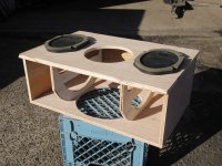
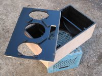
Build pics
Attachments
-
 3.jpg437.7 KB · Views: 90
 -
 5.jpg339.4 KB · Views: 88
 -
 11.jpg364.2 KB · Views: 86
 -
 12.jpg452.9 KB · Views: 88
 -
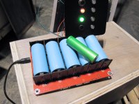 BATTERIES.jpg418 KB · Views: 78
 -
 BATTERIES2.jpg404.9 KB · Views: 73
 -
 BATTERIES3.jpg367 KB · Views: 72
 -
 1.jpg473.9 KB · Views: 111
 -
 2.jpg440.1 KB · Views: 85
 -
 5.jpg430.3 KB · Views: 93
 -
 6.jpg485 KB · Views: 83
 -
 7.jpg647.7 KB · Views: 90
 -
 8.jpg450.5 KB · Views: 95
Hey, that's a nice looking piece, good job!
Yeah, phase matters. But 150 Hz has a fairly long wavelength (relative to physical distances in the project) so it was probably destined to be not too complex. Looks like you did manage to stumble into nice 150 Hz XO =)
Neat that you're taking measurements of it! If you wanted to examine what happened there more closely, you could measure woofer only, mid/tweets only, and then both together. And you could do a measurement of all together with the woofer phase flipped, if you wanted. But that's only really if you wanna look into that woofer XO. It looks like you've got such a nice result you could just call it done and enjoy it.
Nice looking box and finish, Chompy!My main question is; my understanding of crossovers is largely amateur (matching levels), but I hear phase is just as important. Did I just stumble upon an ideal 150hz crossover, given the controls I have and the drivers I'm using?
Smooth phase response results in smooth frequency response in the crossover region, so yes, phase is important.
Without seeing the response of the LF section separate from the mid/high, can't say the crossover is "ideal", but the transition looks fine as presented.
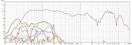
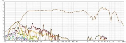
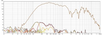
Though the mid-high region looks totally different between the #1 and the two #3 posts, the dip around 3kHz and the rapid 360 degree shift in that region suggest that the polarity of the tweeters should be reversed to correct the response.
That said, if their "crossover" is just a capacitor on the tweeter, that response might be as good as it gets without a lot of work.
Art
Thank you for the feedback! It got picked up today so no more measurements, but the customer seemed very happy. I'll take more & better measurements in the future. Speaking of; should I be using the little tripod stand that came with the umik-1, or laying it flat on the ground on a cloth?
Next up is a dayton classic 6.5" micro sub which should be finished in a few days.
Next up is a dayton classic 6.5" micro sub which should be finished in a few days.
Attachments
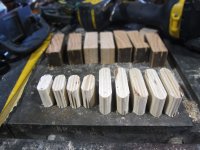
Quick update in case anyone wanted to see the backs of the mid/tweet drivers; here is what they look like right out of a car. I haven't tried to break one open to see what the crossover looks like. XW7F-18808-GA 4Ω 25W


I finished construction on my 6.5" sub (DCS165-4, 1/2"/13mm baltic birch, ~0.3ft3/8.6L, 45-50hz tuning, wood grill).
I need to run more tests but I think I may have a bad driver. It sounds distorted even at low volume. I'll measure the driver freeair with my dats tomorrow (I never bothered... woops! Bought it open box for cheap so not worried about the cost, but now I wish I had checked it before starting a box for it...) as well as measuring the response in the box (with and sealed port, in case my 'firing a calculated short distance from the inside back wall to extend the port' design is faulty). It's not the grill rattling or hitting the surround, as I tried removing it.
All I have so far is an impedance trace, which I think matches reasonably well to my (admittedly factory spec based) model, at least going by the frequencies of the peaks (Is that what I should be looking at? How important/meaningful are the heights of the peaks?).
Attachments
Last edited:
Smart looking builds, nice work 👍
The Impedance curve does tell you a couple of useful things.
First, the port tuning corresponds to the dip between the 2 main peaks, so you've pretty much nailed your 45Hz target already.
Second, the relative height of the 2 peaks tells you whether the port tuning is higher or lower than the drivers Fs. With the lower peak at a lower height as in your measurement, that means port tuning is lower than driver Fs (& vice versa). That your measured Fs is slightly higher than factory spec is not too unusual, often it will settle back closer to factory spec as the driver is run in a bit.
Third, the overall height of the peaks can tell us how well the box + port combination is resonating - if the peaks were substantially lower in height than the model, that would imply a lossy system (eg leaky box, port tube made out of too flimsy a material etc) and you'd see less output around port tuning frequency. You can see the effects of this in your model if you can find where Hornresp has its "Ql" parameter - a value of 7 is a common default for a well made box, lowering it simulates more losses and less port output.
Fourth, you have at least one small unintended resonance happening around 250Hz, based on the little extra peak in the impedance there. I'm not experienced enough to predict what's causing it unfortunately, but the things I would look at checking are: how well the driver is sealed to the cab (making sure you have nice even pressure on all the mounting bolts and that the gasket is sealing well; whether there is any panel flex in the cab (not sure if you have any bracing in yet, it may not seem needed for such a small box but the 2 sides at least might benefit from being tied together with a crossbrace); it's good you've already eliminated the grille as that would've been another possible suspect.
Hope this helps,
David.
Thank you! I appreciate the details on how to read the impedance chart. And yep, there's one brace in there tying the two largest sides together. I ran my wire through it to help keep it away from the walls. The port tube is PL'd to the bottom of the box as well (so it shouldn't be vibrating).Smart looking builds, nice work 👍

Should get some more info today!
I am sure! Can you be more specific?I think you did a very good job but there are still some improvements needed.
Looks like it will be tonight before I can make any serious noise, but I redid the seal behind the driver and I think it sounds better so far; fingers crossed it was just an air leak. The blip at ~250hz is almost gone.

Here is before and after overlaid:

Does the general raising of the minimum impedance (yet slightly lower peaks) make sense with sealing up a leak?
On a side note; on one of my computers DATS refuses to show the impedance curve when opening (or importing) the same saved files which show up fine on the computer I measured from. Anyone run across this? Software versions matched but I also tried updating the problematic one to the newest; same result.

Here is before and after overlaid:
Does the general raising of the minimum impedance (yet slightly lower peaks) make sense with sealing up a leak?
On a side note; on one of my computers DATS refuses to show the impedance curve when opening (or importing) the same saved files which show up fine on the computer I measured from. Anyone run across this? Software versions matched but I also tried updating the problematic one to the newest; same result.
Last edited:
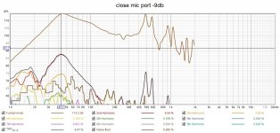
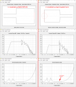
I don't know what to think; whether I still have an air leak, or a bad driver. Attached is a close mic recording of the tail end of a downward sweep, roughly 60-35hz, with most of the fundamental filtered out. You can hear an unpleasant noise growing throughout the recording, and this is at fairly low power. Also attached are some close mic measurements of the woofer and port, but they are at different levels (so as not to max out the mic), so may be useless.
FWIW I never expected it to handle full power below tuning (I kind of designed it to take a pair of FMOD 50hz highpass filters if needed, in case the end user wants to go nuts with it), but this isn't even moving the cone much!
FWIW I never expected it to handle full power below tuning (I kind of designed it to take a pair of FMOD 50hz highpass filters if needed, in case the end user wants to go nuts with it), but this isn't even moving the cone much!
Attachments
I'm at a loss with my DCS165 sub. I have a list of things that didn't appear to be the problem, but it still doesn't sound good, IMO.
#1 The driver. I thought it was my open-box driver, because it took a very small amount of off-center pressure to get the voice coil to rub. I got a brand new driver in, and it behaves and sounds exactly the same.
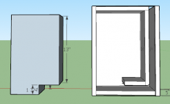
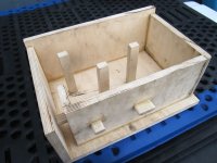
#2 The inside end of the port. I was trying for a controlled distance from the inside of the box, to lengthen the port a bit. Math at the end.
Assuming that was the problem, I first tried a strip of sandpaper cut from a belt, 'flossing' the inside end to sand it down a little, and round it over. That didn't seem to fix it.

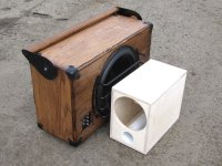
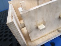
So I cut most of the end off the box, and took off another half inch or so from the port, at an angle.


Made a new back plate, with a bit of cutout for even more space around the port. (the hole is for the terminal cup).


That didn't seem to fix it either. It might sound a bit better, but I can't say for sure.
#3: The terminal cup. On the chance that it was vibrating or rattling, I swapped it out for a blank piece of wood with a relief for the wires, and lots of noncuring silicone caulk. No change.

#4 Finally, I figured maybe it was just port chuff; the port could be bigger, though it's the same size (~2inch, mostly unflared) as in the kit PE sells. Figured I should find out how much power it's getting. Stuck a multimeter on the leads while playing a tone at the impedance minimum (44hz, 3.7ohm) and measured ~10v. (Do I need to multiply this value by root 2 because I'm using a cheap multimeter?) That should be around 30 watts; according to my models the port air velocity should be under 18m/s at that power. But I'm hearing a clear and obvious noise even before this level.
#5 an air leak. I can depress the driver, close off the port with my hand, and wait for a slow count of five and the driver stays in, then bounces out when I release the port.
Possibilities:
#1 The port is still too close on the inside end, thus air is (still) chuffing against the back wall.
#2 The port is vibrating. It's 2" PVC, PL 3x glued to the box along the entire length. Is that enough or do I need a brace on it, somewhere toward (but not right at) the inside end?
#3 Something else / Aliens!
Original design:

With modifications:

Final impedance sweep with modifications:

I see the ~250hz blip is still there. The small blip around 500hz could be port resonance.
-----------------------------------
Port math:
2" inside diameter port has a radius of 1", making it a unit circle, making the math very simple.
CSA (area) is Pi*r^2 = 1Pi = ~3.14in2
Perimeter is 2*Pi*r = 2pi
To keep the area constant, I originally put the port exactly 1/2" from the back wall. This ring should have an area of height * perimeter = 0.5" * 2pi= 1Pi = ~3.14in2, same as the CSA. I know this sounds extremely close, but I thought this is where it would have to be to extend the port.
I know at least one way my design was compromised from the start: because the port lays up against one wall, it isn't radiating into 'free air' all the way around.
-----------
Suggestions, questions, or measurements I need to take?
#1 The driver. I thought it was my open-box driver, because it took a very small amount of off-center pressure to get the voice coil to rub. I got a brand new driver in, and it behaves and sounds exactly the same.
#2 The inside end of the port. I was trying for a controlled distance from the inside of the box, to lengthen the port a bit. Math at the end.
Assuming that was the problem, I first tried a strip of sandpaper cut from a belt, 'flossing' the inside end to sand it down a little, and round it over. That didn't seem to fix it.
So I cut most of the end off the box, and took off another half inch or so from the port, at an angle.
Made a new back plate, with a bit of cutout for even more space around the port. (the hole is for the terminal cup).
That didn't seem to fix it either. It might sound a bit better, but I can't say for sure.
#3: The terminal cup. On the chance that it was vibrating or rattling, I swapped it out for a blank piece of wood with a relief for the wires, and lots of noncuring silicone caulk. No change.
#4 Finally, I figured maybe it was just port chuff; the port could be bigger, though it's the same size (~2inch, mostly unflared) as in the kit PE sells. Figured I should find out how much power it's getting. Stuck a multimeter on the leads while playing a tone at the impedance minimum (44hz, 3.7ohm) and measured ~10v. (Do I need to multiply this value by root 2 because I'm using a cheap multimeter?) That should be around 30 watts; according to my models the port air velocity should be under 18m/s at that power. But I'm hearing a clear and obvious noise even before this level.
#5 an air leak. I can depress the driver, close off the port with my hand, and wait for a slow count of five and the driver stays in, then bounces out when I release the port.
Possibilities:
#1 The port is still too close on the inside end, thus air is (still) chuffing against the back wall.
#2 The port is vibrating. It's 2" PVC, PL 3x glued to the box along the entire length. Is that enough or do I need a brace on it, somewhere toward (but not right at) the inside end?
#3 Something else / Aliens!
Original design:
With modifications:
Final impedance sweep with modifications:
I see the ~250hz blip is still there. The small blip around 500hz could be port resonance.
-----------------------------------
Port math:
2" inside diameter port has a radius of 1", making it a unit circle, making the math very simple.
CSA (area) is Pi*r^2 = 1Pi = ~3.14in2
Perimeter is 2*Pi*r = 2pi
To keep the area constant, I originally put the port exactly 1/2" from the back wall. This ring should have an area of height * perimeter = 0.5" * 2pi= 1Pi = ~3.14in2, same as the CSA. I know this sounds extremely close, but I thought this is where it would have to be to extend the port.
I know at least one way my design was compromised from the start: because the port lays up against one wall, it isn't radiating into 'free air' all the way around.
-----------
Suggestions, questions, or measurements I need to take?
Last edited:
Close off the port, push in the woofer and release. The cone should return in a few seconds. If it immediately returns, you have a leak.I don't know what to think; whether I still have an air leak, or a bad driver. Attached is a close mic recording of the tail end of a downward sweep, roughly 60-35hz, with most of the fundamental filtered out. You can hear an unpleasant noise growing throughout the recording, and this is at fairly low power. Also attached are some close mic measurements of the woofer and port, but they are at different levels (so as not to max out the mic), so may be useless.
Remove the woofer from the box, play sine waves of 20 - 50 Hz at which the cone moves 2 mm and listen for unwanted noises. Other than the sine wave, it should be silent or have minor chuffing from its vents.
Having the port parallel to a wall is fine. Having the port exit near the opposing wall is not ideal for chuffing, but should not be a problem at low and medium listening levels.
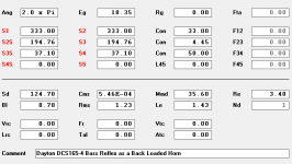
I suggest you model your box once again in hornresp not as bass reflex but as a "back loaded horn", with the port being the last horn segment. this may provide a more evident behaviour of port and enclosure resonances. see attached example.Suggestions, questions, or measurements I need to take?
Attachments
Holds negative pressure fine: "#5 [not an] air leak. I can depress the driver, close off the port with my hand, and wait for a slow count of five and the driver stays in, then bounces out when I release the port."Close off the port, push in the woofer and release. The cone should return in a few seconds. If it immediately returns, you have a leak.
Driver sounds good freeair at at far more than 2mm each way. Tested at 20 and 40 hz. Clean and quiet.Remove the woofer from the box, play sine waves of 20 - 50 Hz at which the cone moves 2 mm and listen for unwanted noises. Other than the sine wave, it should be silent or have minor chuffing from its vents.
Thank you, that was my understanding as well :/ Unfortunately there seems to be a problem even at low levels. Would an audio recording help?Having the port parallel to a wall is fine. Having the port exit near the opposing wall is not ideal for chuffing, but should not be a problem at low and medium listening levels.
FWIW I'm rebuilding it in 3/4" BB; with a little bigger net volume and a lot larger port.
Thank you! I have done that once before to model a tapered slot, but didn't think of it for this case. Looks like that can explain where my 'blips' (up above the passband) in the impedance graphs are coming from? I wasn't worried about those, just mentioned them in case they help diagnose the nasty noise I'm getting down around and under the tuning frequency, even at low levels.I suggest you model your box once again in hornresp not as bass reflex but as a "back loaded horn", with the port being the last horn segment. this may provide a more evident behaviour of port and enclosure resonances. see attached example.
FWIW I'm rebuilding it in 3/4" BB; with a little bigger net volume and a lot larger port.
Maybe something is rattling? It could be the cable rattling against something solid, two pieces of wood that lay against each other without being glued, the same for port + wood and finally, the woofer against the baffle. If not, I am out of suggestions.
Worth a shot!Would an audio recording help?
I still have not figured out what is wrong with my small box or my two dayton dcs165-4 drivers. I build a slighly larger box with a larger port, and the daytons sound bad in it as well. Here are the details for it; no test results other than listening.
I then picked up a completely different driver which sounds great... (next post)
I then picked up a completely different driver which sounds great... (next post)
Attachments
-
 0 inside.PNG4.5 KB · Views: 76
 -
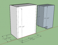 0 dimensions and airspace.PNG6.8 KB · Views: 84
 -
 1 spacers.jpg335 KB · Views: 82
 -
 2 braces and spaces.jpg340.9 KB · Views: 76
 -
 3 braces and spaces 2.jpg298.8 KB · Views: 69
 -
 4 2nd to last panel clamps.jpg383.5 KB · Views: 67
 -
DCS165 BLH.txt1 KB · Views: 79
-
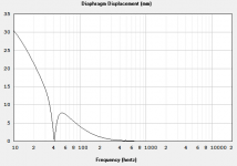 hornresp displacement.PNG3.1 KB · Views: 67
 -
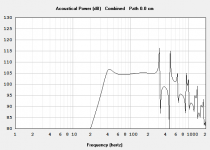 hornresp reponse.PNG3.5 KB · Views: 55
 -
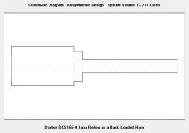 hornresp schematic.PNG1.5 KB · Views: 64
 -
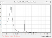 hornresp velocity.PNG4 KB · Views: 57
 -
 hornresp.PNG3.1 KB · Views: 60
Bought a DS18 ZR6.4D which looked like it could work in the same box.


1m outside testing looks good, so I kept working on the box. Grille is made from solid fiberglass rod.


Complete


Size compared to previous


I really don't know if I have two bad dayton drivers, or I am just expecting too much out of them. Still planning to get an audio recording of them and do some further testing; for now I'm just happy to be done with the project.
1m outside testing looks good, so I kept working on the box. Grille is made from solid fiberglass rod.
Complete
Size compared to previous
I really don't know if I have two bad dayton drivers, or I am just expecting too much out of them. Still planning to get an audio recording of them and do some further testing; for now I'm just happy to be done with the project.
Attachments
Last edited:
- Home
- Loudspeakers
- Subwoofers
- I built a portable with a 12" passive radiator