Hello!, have some questions for the Hypex UcD700HG with HxR linear power supply, especially the Vdr circuit I've added to the stock S700 power supply.
TLDR It is ok for the UcD700 Vdr circuit and regulator of choice shown in the schematic below?, or should I add another small transformer solely to power the Vdr circuit? as I've seen on some builds, I asking because the xformer tabs used will be shared with some relays and two 24V fans and I'm worried that may introduce noise etc, although the fans will only be activated by independent heatsink thermal sensors set to close at 45~50deg so they will be off most of the time.
After recent Samson S700 amp failure denoted on this thread I've finally opted to modify it with Class D amp modules rather than fully restoring it with equivalent transistors, or even designing/ordering new PCB's with newer amp topology, time consuming and need lots of parts plus protection circuitry etc.
So I'm leaning toward 2x Hypex UcD700HG with HxR since they use split(+/-) voltage unlike the ICEpower 500A, and because it seems to have good reviews around the web, plus the Samson S700 stock power supply specs seems to be ok for them, it will be used as midbass amplifier.
The S700 Transformer Spec are as follow:
HV:
Pri: 120VAC BRN/GRY
Sec: 58VAC CT RED/YEL/RED
LV:
Sec: 22VAC GRN/GRN
Sec: 22VAC CT YEL/BLU/YEL
The VA is unknown but the transformer weighted almost ~15.5LBS so I guesstimate is around ~750VA or so.
Also the 22V tabs I will be using for the Vdr is the one who powers the step-start plus two 24v fans so I guess should have more than ~500mA, the other 22V tabs are center tapped but will be already used for the front panel metering and the +/-VSIG.
Here is the slightly modified/simplified stock S700 power supply with some added bits for the UcD700:
Regards
EDIT: Found some errors in the schematic due the cut/copy/paste edition, I will design a simpler schematic in EasyEDA and order some premade PCB's for simplicity, then update this thread after testing them.
TLDR It is ok for the UcD700 Vdr circuit and regulator of choice shown in the schematic below?, or should I add another small transformer solely to power the Vdr circuit? as I've seen on some builds, I asking because the xformer tabs used will be shared with some relays and two 24V fans and I'm worried that may introduce noise etc, although the fans will only be activated by independent heatsink thermal sensors set to close at 45~50deg so they will be off most of the time.
After recent Samson S700 amp failure denoted on this thread I've finally opted to modify it with Class D amp modules rather than fully restoring it with equivalent transistors, or even designing/ordering new PCB's with newer amp topology, time consuming and need lots of parts plus protection circuitry etc.
So I'm leaning toward 2x Hypex UcD700HG with HxR since they use split(+/-) voltage unlike the ICEpower 500A, and because it seems to have good reviews around the web, plus the Samson S700 stock power supply specs seems to be ok for them, it will be used as midbass amplifier.
The S700 Transformer Spec are as follow:
HV:
Pri: 120VAC BRN/GRY
Sec: 58VAC CT RED/YEL/RED
LV:
Sec: 22VAC GRN/GRN
Sec: 22VAC CT YEL/BLU/YEL
The VA is unknown but the transformer weighted almost ~15.5LBS so I guesstimate is around ~750VA or so.
Also the 22V tabs I will be using for the Vdr is the one who powers the step-start plus two 24v fans so I guess should have more than ~500mA, the other 22V tabs are center tapped but will be already used for the front panel metering and the +/-VSIG.
Regards
EDIT: Found some errors in the schematic due the cut/copy/paste edition, I will design a simpler schematic in EasyEDA and order some premade PCB's for simplicity, then update this thread after testing them.
Last edited:
I've ended up designing my own UcD700/2k control board to simplify the Samson amp conversion, though the board should work for other old amps as well.
The board is made to provide easy connections hookup through JST-XH headers, plus speaker protection in the event of a module DC-Protect/Error detection as this is mainly designed to use with linear power supply(s) rather than the recommended Hypex switching power supply.
Also since most old class a/b amplifiers already comes with split(+/-) voltages for both HV for the output and LV for the signal, the control board will include a simple VDR circuit to provide the +15V through a 1% precision TL780-15x regulator per module.
The simple protection circuit consist of an SFH617A-4 optocoupler and a 2N3904 transistor to activate/latch a relay that will disable the speaker and the module on/off relays, and will remains latched until a power cycle.
I've simulated the protection circuit functionality on LTspice with good results, though I will order the PCB's from EasyEDA to test the board functionality before ordering the UcD700HG amp modules from Hypex/DIYclassd just to be sure.
The pinouts are as follow:
CN1 (Connect to UcD700/2k J10)
Referenced to the UcD700/2k J10 header.
CN2 (LV power input header)
1) +24v for the onboard Vdr regulator and protection circuit
2) +24v (time delay) for the K1/K3 relays
3) +VSIG
4) GND
5) -VSIG
CN3 (Utility header)
1) NC
2) GND
3) NC
4) Protection monitor/led
5) NC
6) AF signal monitor
CN4 (Alt header)
Alternative input signal and on/off control
JP1 (Protection circuit enable/disable)
1-2 enables the protection circuit
2-3 disables the protection circuit
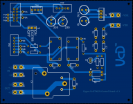
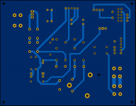
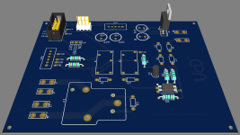
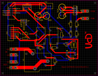
Here is the proto UcD700/2k control board preview:


Regards!
The board is made to provide easy connections hookup through JST-XH headers, plus speaker protection in the event of a module DC-Protect/Error detection as this is mainly designed to use with linear power supply(s) rather than the recommended Hypex switching power supply.
Also since most old class a/b amplifiers already comes with split(+/-) voltages for both HV for the output and LV for the signal, the control board will include a simple VDR circuit to provide the +15V through a 1% precision TL780-15x regulator per module.
The simple protection circuit consist of an SFH617A-4 optocoupler and a 2N3904 transistor to activate/latch a relay that will disable the speaker and the module on/off relays, and will remains latched until a power cycle.
I've simulated the protection circuit functionality on LTspice with good results, though I will order the PCB's from EasyEDA to test the board functionality before ordering the UcD700HG amp modules from Hypex/DIYclassd just to be sure.
The pinouts are as follow:
CN1 (Connect to UcD700/2k J10)
Referenced to the UcD700/2k J10 header.
CN2 (LV power input header)
1) +24v for the onboard Vdr regulator and protection circuit
2) +24v (time delay) for the K1/K3 relays
3) +VSIG
4) GND
5) -VSIG
CN3 (Utility header)
1) NC
2) GND
3) NC
4) Protection monitor/led
5) NC
6) AF signal monitor
CN4 (Alt header)
Alternative input signal and on/off control
JP1 (Protection circuit enable/disable)
1-2 enables the protection circuit
2-3 disables the protection circuit
Here is the proto UcD700/2k control board preview:


Regards!