Hello Class D experts.
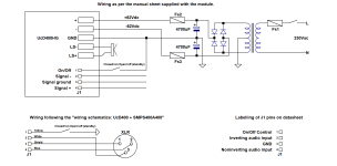
I have two Hypex UcD400HG modules with which I will construct two monoblocks with linear +/- 62V power supplies (which I already have). There are some connection issues arising that I cannot square with the Hypex paper "Dealing with legacy pin 1 problems".
1. On the manual sheet supplied with the module, in the "typical connections" diagram, connector J1/pin 3 is labelled as "Signal ground", but there is no indication of where it should be connected . This is weird - according to the Hypex paper, with a differential audio input, there should be no "signal ground" connection. (Signal + and signal - inputs are provided). A "signal ground" in addition to a differential input makes no sense.
Just to muddy the waters, the document "wiring schematics: UcD400 + SMPS400A400" shows J1/pin 3 connected to the shield and input XLR/pin 1. This also makes no sense, given that the Hypex paper makes it clear that the XLR/pin 1 should be connected to the chassis only, near to the socket.
Additionally, the datasheet labels J1/pin 3 as "GND".
What gives here? To what should I connect J1/pin 3: the "signal ground" (whatever that is); XLR/pin1 and shield; the amp's common GND; leave it unconnected? To what should I connect XLR/pin 1: the chassis only; the module's J1/pin 3 only; both?
I've attached a drawing which illustrates this.
2. There is no earth connection for the mains input shown. My expectation is that the chassis should be connected to mains earth. Is this correct?
3. Is it correct that the common ground points shown on my schematic with the triangular 0V symbol (e.g. the mid-point of the electrolytics) must not be connected to the chassis?
4. Am I taking any unnecessary risks if omit Fs2/Fs3, which are shown on the "typical connections" diagram? There's a fuse on the mains Live input, there's current limiting in the UcD module, and I am wondering what on earth happens if one blows but not the other.
