Hi.
I found this amplifier some time ago and thought it was time to give it a try.
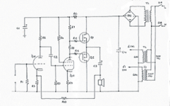
The original was wired point-to-point.
The transformer, 35-0-35v, was shared between both channels.
I propose to make a dual mono amp.
R1/10=47k C1=100uF/100v
R2=220k C2=100nF/250v
R4=33k C3=100uF/63v
R5=820k C4=4700uF/100v
R6/11=1K
R7=4k7, 1W
R8/9=150r
R12/13=100r
V1=ECL86
Q1/Q2= 2SK135/2SJ50
One thing I think should be done is to separate the supply to the driver from the output stage.
Also required is a slow start/anti-thump.
Any other improvements?
Thanks
Andy
I found this amplifier some time ago and thought it was time to give it a try.
The original was wired point-to-point.
The transformer, 35-0-35v, was shared between both channels.
I propose to make a dual mono amp.
R1/10=47k C1=100uF/100v
R2=220k C2=100nF/250v
R4=33k C3=100uF/63v
R5=820k C4=4700uF/100v
R6/11=1K
R7=4k7, 1W
R8/9=150r
R12/13=100r
V1=ECL86
Q1/Q2= 2SK135/2SJ50
One thing I think should be done is to separate the supply to the driver from the output stage.
Also required is a slow start/anti-thump.
Any other improvements?
Thanks
Andy
Attachments
I think it looks great, and it also seems like a great idea. I have been thinking about a similar project for a while now. But when it comes to exact suggestions about your design I am afraid my current knowledge is not really enough. I need to learn more about mosfets and tubes.
poynton said:Hi.
No-one got any comments / suggestions for improvements?
Andy
Honestly? I would forget about connecting the tube and MOSFET stage the way it is in that schematic, and especially powering it from the same power supply. Why? Have a go at estimating the output swing of this amp... and what limits it.
ilimzn said:
Honestly? I would forget about connecting the tube and MOSFET stage the way it is in that schematic,
Why?
and especially powering it from the same power supply.
I have read that this should be done which is why I put it in the original post.
Unfortunately, my knowledge of tubes is limited which is why I posted . Please explain.Why? Have a go at estimating the output swing of this amp... and what limits it.
Andy
Try running the loadlines for that voltage and load resistance on the tube's curves. That should illuminate things.
I'm not an expert on MOSFETs, but it doesn't look to me like the biasing will work, either. You may also wish to consider what the source impedance of the tube driver is, compare with the MOSFET input capacitance, and see what your bandwidth ends up being.
I'm not an expert on MOSFETs, but it doesn't look to me like the biasing will work, either. You may also wish to consider what the source impedance of the tube driver is, compare with the MOSFET input capacitance, and see what your bandwidth ends up being.
SY said:Try running the loadlines for that voltage and load resistance on the tube's curves. That should illuminate things.
As I said, I have a limited knowledge of tubes
I'm not an expert on MOSFETs, but it doesn't look to me like the biasing will work, either. You may also wish to consider what the source impedance of the tube driver is, compare with the MOSFET input capacitance, and see what your bandwidth ends up being.
This output configuration is used in several schematics I've seen. Of course, that does not make it correct but it must work.
the_manta said:
Furthermore these Mosfets are rare. Buzt can be replaced by BUZ900 ... and so forth
Regards, Simon
I have enough for several amps !!
Andy
poynton said:
I have enough for several amps !!
Lucky guy....

Did you see this thread ? Your Mosfets will work well with it ! Only thing you need is a seperate PSU for the t00bz.
Regards, Simon
- Status
- Not open for further replies.
- Home
- Amplifiers
- Tubes / Valves
- Hybrid Tube / Mosfet Amplifier