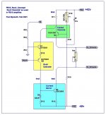
Hi, I am trying to create a circuit to drive a push-pull VAS with a non-differential signal from an op amp. The output of the AO has as maximum values +-vin (much lower than the supply voltage of the VAS) so I thought of adding two DC components to this signal:
VDC1 = Vcc-k * vbe (Qvas) and VDC2 = Vee - k * vbe (Qvas)
Where k is greater than 1 to implement later a simple current source and active load on the VAS with an emitter resistor. Also Vdc1 = -Vdc2.
My idea was to use a circuit like the one in figure 1, but apparently I am wrong in some important concept because it does not work at all in the way I want, additionally looking around I´ve found some similar circuits but those use two diodes in series from the collector of Q1 to the collector of Q2 (figure 2) and this confuses me: doesnt this limit the maximum excursion in each collector to vin + -2 * Vd at the same time they increase the power dissipated in Q3 and Q4 in the absence of input signal? (the power supply of figure 2 is + -90Vdc).
I will appreciate any help or clue you can give me in this regard, I am not interested in the exact values I want to understand how to calculate them, and if there are any important considerations to make.
PD: sorry for my caveman-level english 🙁
Attachments

Last edited:
Have you seen this thread - LaFet Amp based on Philips AH578 ?
It uses a op-amp input to drive vas stage.
It uses a op-amp input to drive vas stage.

>Lucian, Here are some ideas that will work.
This is almost identical to schematics from this thread -
one of many examples:
https://www.diyaudio.com/forums/solid-state/357369-unusual-amp-1987-a-137.html#post6528812
This is almost identical to schematics from this thread -
one of many examples:
https://www.diyaudio.com/forums/solid-state/357369-unusual-amp-1987-a-137.html#post6528812
Have you seen this thread - LaFet Amp based on Philips AH578 ?
It uses a op-amp input to drive vas stage.
Thanks for the response!. That circuit it´s exactly the first iteration that i designed (not that i´ve seen that thread before) ... then i added the constant current sources and messed up things because i beggining to need impractical values of resistance and current.
Lucian,
Here are some ideas that will work.
Regards,
Paul Bysouth
i was thinking about a diammond configuration but i´d never seen this topologies before, seems to me that they can have an insane slew-rate.
Definitively i'm gonna be experimenting on it.
Thank you very much!
>Lucian, Here are some ideas that will work.
This is almost identical to schematics from this thread -
one of many examples:
https://www.diyaudio.com/forums/solid-state/357369-unusual-amp-1987-a-137.html#post6528812
great! seems there's a ton of variety examples in that thread, i´m gonna take a further look when i get some more time. Thanks!