as you know the input sensitivity of the CFP (Sziklai connection)
is higher than normal EF output stage
because inside it there is a very big gain
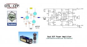
as you know the quality of the scene produced by an OTL stadium-style (Futterman)
is higher than normal SRPP
because there are two active devices
this is an evolution of famous Bartolomeo Aloia GY-50
is higher than normal EF output stage
because inside it there is a very big gain
as you know the quality of the scene produced by an OTL stadium-style (Futterman)
is higher than normal SRPP
because there are two active devices
this is an evolution of famous Bartolomeo Aloia GY-50
Attachments
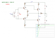
pure CFP
you can see a good application of Sziklai CFP output stage here
http://francis.audio2.pagesperso-orange.fr/LFA50.doc
see emitter resistors on drivers😎
you can see a good application of Sziklai CFP output stage here
http://francis.audio2.pagesperso-orange.fr/LFA50.doc
see emitter resistors on drivers😎
Attachments
Member
Joined 2009
Paid Member
I simulated a design like this last year - it's an interesting circuit but I haven't built it yet.
can you post simulation's results?
http://www.esafono.it/pre50V.pdf
here there is another indipedent CFP with LED current source😉
http://www.esafono.it/pre50V.pdf
here there is another indipedent CFP with LED current source😉
Attachments
Member
Joined 2009
Paid Member
Post it ? Well, I was going to wait until it's in a more mature state before throwing it out to the wolves. I'm looking only at the output stage, looking for options to use very little gnf and accept higher distortion as a result. The CFP provides a lot of local feedback to keep the output more linear. The issue is turn-on and turn-off of the CFP which the emitter resistor topology your circled can help with. When my current project is done I'll revisit and let you know if I have something useful to share.
Are you actually going to build one of these ?
Are you actually going to build one of these ?
yes i'm working around
to check real sensitivity (good for tube's driver) 😉
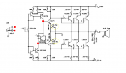
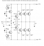
another good CFP comes from Musical Fidelity XA-50
you can find it on ebay
POWER AMPLIFIER KIT - BASED ON MUSICAL FIDELITY X-A50! su eBay.it, Other, Computers Networking
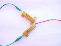
normally use Sanken final devices A1186 and C2837
(probably for Vbe - is the same in each rail)
with famos driver triplet
H649A H669A H669A
similar to MJ340/MJ350
to check real sensitivity (good for tube's driver) 😉
another good CFP comes from Musical Fidelity XA-50
you can find it on ebay
POWER AMPLIFIER KIT - BASED ON MUSICAL FIDELITY X-A50! su eBay.it, Other, Computers Networking
normally use Sanken final devices A1186 and C2837
(probably for Vbe - is the same in each rail)
with famos driver triplet
H649A H669A H669A
similar to MJ340/MJ350
Attachments
Literally every circuit in this thread has some sort of error, some are catastrophic.
First, NONE except the last one are really CFPs. A CFP 'collector' is made up by connecting the first (input) transistor emitter and the second (output) transistor collector to a single point. Such a compound transistor still needs an emitter resistor to stabilize it's working point. When connected this way the bias network only has to have thermal contact with the first transistor. Note that none of the circuits above do this, they all must have the bias network in thermal contact with the output transistor heatsink, and in most cases the drivers need to share this heatsink too. Too bad in some circuits here the bias network has no thermal compensation at all, or even worse, no way of defining the standing current at all. Others have standing current trim that will immediately destroy the whole output stage if the trimmer wiper loses contact even momentairly. Yet others have gain, which seems to completely be missed by most posters, so they are not just followers/buffers but complete amplifiers.
And, that 'OTL' schematic with a concertina phase splitter is just plain wrong. The top output triode is a follower with gain 1, the bottom works as a grounded cathode amp so with a gain much larger than 1 - hence impossible to connect as a totem-pole push-pull and have it work with anything approaching symmetry.
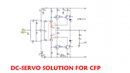
Oh and that 'DC servo' is nothing of the sort, rather a bootstrap connection to increase the input impedance of the BJT buffer stage. Too bad the point of it has been missed because it cannot increase the impedance past that of the DC balance trimmer, which is not bootstrapped. Incidentally this is the only proper CFP schematic, too bad about the tube part....
All of this just goes to show you cannot trust everything you find on the net, and if you can trust something, you can't just go splicing bits and pieces together without understanding how they work.
First, NONE except the last one are really CFPs. A CFP 'collector' is made up by connecting the first (input) transistor emitter and the second (output) transistor collector to a single point. Such a compound transistor still needs an emitter resistor to stabilize it's working point. When connected this way the bias network only has to have thermal contact with the first transistor. Note that none of the circuits above do this, they all must have the bias network in thermal contact with the output transistor heatsink, and in most cases the drivers need to share this heatsink too. Too bad in some circuits here the bias network has no thermal compensation at all, or even worse, no way of defining the standing current at all. Others have standing current trim that will immediately destroy the whole output stage if the trimmer wiper loses contact even momentairly. Yet others have gain, which seems to completely be missed by most posters, so they are not just followers/buffers but complete amplifiers.
And, that 'OTL' schematic with a concertina phase splitter is just plain wrong. The top output triode is a follower with gain 1, the bottom works as a grounded cathode amp so with a gain much larger than 1 - hence impossible to connect as a totem-pole push-pull and have it work with anything approaching symmetry.
Oh and that 'DC servo' is nothing of the sort, rather a bootstrap connection to increase the input impedance of the BJT buffer stage. Too bad the point of it has been missed because it cannot increase the impedance past that of the DC balance trimmer, which is not bootstrapped. Incidentally this is the only proper CFP schematic, too bad about the tube part....
All of this just goes to show you cannot trust everything you find on the net, and if you can trust something, you can't just go splicing bits and pieces together without understanding how they work.
Thanks ilimzn
wrong Capacitor on CFP
see now the correction🙄
the first problem of CFP is the self-oscillation
best solution that I have found
without difference of sound
it's adding a POWER RESISTOR on output😉
see OTL now, with ground input reference 😎
wrong Capacitor on CFP
see now the correction🙄
the first problem of CFP is the self-oscillation
best solution that I have found
without difference of sound
it's adding a POWER RESISTOR on output😉
see OTL now, with ground input reference 😎
Attachments
Last edited:
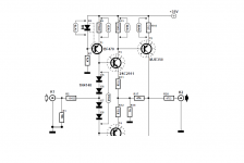
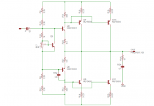
Finally CFP !
See schematic..
So let's say if you put the CFP emeitter resistor in the ESP project CFP, You may eliminate the CFP collector resistor (bridge it). At most you could put a small driver-only emitter resistor for stabilty. What do you think?Literally every circuit in this thread has some sort of error, some are catastrophic.
First, NONE except the last one are really CFPs. A CFP 'collector' is made up by connecting the first (input) transistor emitter and the second (output) transistor collector to a single point. Such a compound transistor still needs an emitter resistor to stabilize it's working point. When connected this way the bias network only has to have thermal contact with the first transistor.
See schematic..
Attachments
if you have a VAS
then need a Feedback
as GY-50 output stage must be gain G=1 😀
probably it's a good idea add the original D6 and D7 to protect finals
then need a Feedback
as GY-50 output stage must be gain G=1 😀
probably it's a good idea add the original D6 and D7 to protect finals
Attachments

Last edited:

- Status
- Not open for further replies.
- Home
- Amplifiers
- Solid State
- Hybrid amp Aloia GY-50 "a step beyond of"