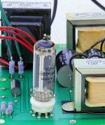
My EL84 has a bit of "hum", or more accurately, "120Hz noise".
The 300V B+ power supply uses a split-secondary Edcor power transformer with full wave rectification (two diodes). The B+ is made henceforth:
1. Transformer
2. 200mA fuse
3. Full wave diode rectification
4. 100 Ohm resistor (to limit peak transformer current)
5. 2.2uF Film capacitor
6. 470uF 450V electrolytic capacitor
7. MOSFET voltage regulator
8. 470uF 450V electrolytic capacitor
9. 8mH toroidal choke (damps high frequency components)
10. 2 x 12uF Film capacitor
The filament uses a 12.6V winding on the same power transformer. I have used both AC and DC on the filaments and get the same problem. The DC filter looks like this:
1. Transformer (12.6V secondary)
2. Full wave bridge
3. 0.1uF at the bridge
4. 1 Ohm resistor (adjusted as necessary to control voltage)
5. 10,000uF 25V
6. 5mH Toroidal choke (2.5A maximum current)
7. 10,000uF 25V
8. 0.1uF at the output
I can bypass the entire DC electronics and wire the filament straight to AC.
I use 12.6V across two EL84 filaments in series, consuming 0.76A. The filament reference is tapped between the two EL84 (thereby referencing the filament halfway).
Using my Fostex (high efficiency) speaker, I can hear hum. Not smooth AC hum, but it sounds like 120Hz "spikes" ..tic..tic..tic..tic at 120Hz.
The B+ is squeaky clean.
My first suspension is the high-frequency diode commutation from the B+ rectification is "jumping" across the B+ winding to the filament winding inside of the power transformer.
Any ideas?
Why not go with your intuition and try an AC 6.3v supply from another (separate) transformer? With twisted wiring and a centre ground, you should not hear hum even with high efficiency speakers.
BTW You have grounded one side of your DC heaters..,?
BTW You have grounded one side of your DC heaters..,?
I rewired the power transformer, cleaned up the layout, and removed the Variac from the circuit (used for initial testing). The sound cleaned up a lot.
I can still hear - very faintly - the buzz. I am convinced the diode commutation noise is jumping across the B+ and Filament windings on the transformers (see below). I could use a separate transformer to verify this theory, but the noise is now so small it can only be heard very close to the speaker.
Another solution is to use snubber capacitors across the diodes to suppress commutation noise.
The heater circuit (either AC or DC) is center referenced - the heaters are grounded between the two EL84 output valves.
I can still hear - very faintly - the buzz. I am convinced the diode commutation noise is jumping across the B+ and Filament windings on the transformers (see below). I could use a separate transformer to verify this theory, but the noise is now so small it can only be heard very close to the speaker.
Another solution is to use snubber capacitors across the diodes to suppress commutation noise.
Ringing occurs in AC-DC supplies when the diode is just turning off. Using the 1A, 12.6VAC transformer of the previous example we had a natural ringing frequency of 560kHz. This is much higher than the audio band. However, it is modulated by the power line frequency. A half-wave bridge will "buzz" at the line frequency and a full-wave bridge at twice the line frequency. The ringing frequency acts as a carrier to couple with other circuits.
The heater circuit (either AC or DC) is center referenced - the heaters are grounded between the two EL84 output valves.
Last edited:
My EL84 has a bit of "hum", or more accurately, "120Hz noise".
My first suspension is the high-frequency diode commutation from the B+ rectification is "jumping" across the B+ winding to the filament winding inside of the power transformer.
Any ideas?
I had a similar problem on a pre amp I designed and I had to slug the diodes with a low value capacitor to stop the switching glitches. I used a CRC power supply for B+
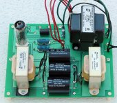
I built an Aikido for a preamp, and used an 6CA4. My most recent EL84 push-pull is the first time I've used solid-state diodes. What a mess!
Pictures attached of the power supply to my Aikido preamp.
I'll install the snubbers tonight, and report on findings.
Pictures attached of the power supply to my Aikido preamp.
I'll install the snubbers tonight, and report on findings.
Attachments
Tweaked the layout a little ...
(quote from Snubber Networks)
... and installed some snubber capacitors on both the filament and B+ solid-state rectifier diodes. I used 0.068uF 50V on the filament diodes and 0.01uF 1200V on the B+ diodes. I'll post pictures tomorrow. The best way would be a 110 Ohm resistor in series with 0.068uF, but I was lazy and omitted the resistor.
The combination of snubber capacitors and improved layout reduced the 120Hz buzz to about the same level as the endemic "hiss" of the amplifier. It is only audible in a quiet room (no HVAC operating) on highly efficient speakers (Fostex) with my ear near (<0.5m) to the speaker.
On inefficient speakers (89dB), the "hiss" is louder than the "buzz".
For all the trouble, I think I prefer vacuum rectification!
(quote from Snubber Networks)
Judicious attention to wiring, loop area, components, and shielding will reduce the ability of the oscillation to couple with other circuits. However, this only attacks the symptoms, not the cause. This is where snubbers come in.
... and installed some snubber capacitors on both the filament and B+ solid-state rectifier diodes. I used 0.068uF 50V on the filament diodes and 0.01uF 1200V on the B+ diodes. I'll post pictures tomorrow. The best way would be a 110 Ohm resistor in series with 0.068uF, but I was lazy and omitted the resistor.
The combination of snubber capacitors and improved layout reduced the 120Hz buzz to about the same level as the endemic "hiss" of the amplifier. It is only audible in a quiet room (no HVAC operating) on highly efficient speakers (Fostex) with my ear near (<0.5m) to the speaker.
On inefficient speakers (89dB), the "hiss" is louder than the "buzz".
For all the trouble, I think I prefer vacuum rectification!
Last edited:
The heater circuits, do they have a reference to ground.
OP says "The heater circuit (either AC or DC) is center referenced - the heaters are grounded between the two EL84 output valves."
So yes...
Get rid of 80% of your PSU capacitance (#6 on your checklist, the capacitor prior to the voltage regulator) and you'll mostlikely get rid of said buzz, if it is indeed caused by the diodes.
While you are at it, there is hardly any point in using 470 uF behind the regulator as well, even though it doesn't burden the transformer directly (except at power on).
While you are at it, there is hardly any point in using 470 uF behind the regulator as well, even though it doesn't burden the transformer directly (except at power on).
The best way would be a 110 Ohm resistor in series with 0.068uF, but I was lazy and omitted the resistor.
You stopped just short of getting a really good result. You have only reduced frequency and amplitude of the ringing. Why not kill it completely?
Yes, I have updated the schematic with proper snubbers.
"Baby steps" ... one improvement at a time ... also aids the learning process to understand each component's contribution! I'm taking my time dialing this amplifier in.
Oh, something to do with the 3.2mV total noise (mostly white noise) on B+ when measured under load! I'm very pleased with the B+ power supply.
The noise is undoubtedly coming from the filaments, either AC or DC. Tweaking the cathode bias balance between the EL84s reduced much of the noise. Brute-force snubbing the diodes on the filaments further reduced the noise, almost inaudible with 100dB sensitivity speakers. Just a few more tweaks (such as proper snubbing with RC network) will finish the job.
"Baby steps" ... one improvement at a time ... also aids the learning process to understand each component's contribution! I'm taking my time dialing this amplifier in.
there is hardly any point in using 470 uF behind the regulator as well
Oh, something to do with the 3.2mV total noise (mostly white noise) on B+ when measured under load! I'm very pleased with the B+ power supply.
The noise is undoubtedly coming from the filaments, either AC or DC. Tweaking the cathode bias balance between the EL84s reduced much of the noise. Brute-force snubbing the diodes on the filaments further reduced the noise, almost inaudible with 100dB sensitivity speakers. Just a few more tweaks (such as proper snubbing with RC network) will finish the job.
Last edited:
- Status
- Not open for further replies.
- Home
- Amplifiers
- Tubes / Valves
- Hum with EL84 Push-Pull