Hi all
I have just spent the last few weekends constructing my latest project. A line preamp with a single stage consisting of a russian 6N6P triode, one half for each channel.
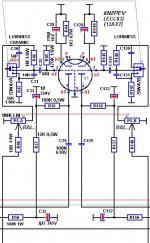
Based on the design at the bottom of this page. TRAM w.
The stage uses output transformers, a pair of Sowter 9650. Sowter type 9560
It sounds fabulous, but I'm plagued with hum pickup from the line output transformers. With no power at all applied to the preamp just plugging in the power amps I have quite loud hum. The secondary windings of the transformers are loaded with a680 ohm resistor and are floating from ground. Grounding the outer of the output RCA makes no difference
If I move the preamp out of the rack and place it out in my room the hum diminishes, but never goes. I'm convinced its hum pickup from a nearby mains field, but I'm astonished how bad it is anywhere near my rack.
I'm thinking I need to shroud the transformers in a mumetal can, not easy.
Anyone have any suggestions please?
I'm thinking
I have just spent the last few weekends constructing my latest project. A line preamp with a single stage consisting of a russian 6N6P triode, one half for each channel.
Based on the design at the bottom of this page. TRAM w.
The stage uses output transformers, a pair of Sowter 9650. Sowter type 9560
It sounds fabulous, but I'm plagued with hum pickup from the line output transformers. With no power at all applied to the preamp just plugging in the power amps I have quite loud hum. The secondary windings of the transformers are loaded with a680 ohm resistor and are floating from ground. Grounding the outer of the output RCA makes no difference
If I move the preamp out of the rack and place it out in my room the hum diminishes, but never goes. I'm convinced its hum pickup from a nearby mains field, but I'm astonished how bad it is anywhere near my rack.
I'm thinking I need to shroud the transformers in a mumetal can, not easy.
Anyone have any suggestions please?
I'm thinking
Does it also hum when lit or just when off?
A picture of your build could give insight in routing troubles.
A picture of your build could give insight in routing troubles.
I got rid of the induced hum in a transformer output preamp by replacing the heater transformer with a switching supply.
But that won't help if it still picks up hum from your power amps nearby.
But that won't help if it still picks up hum from your power amps nearby.
Does it also hum when lit or just when off?
A picture of your build could give insight in routing troubles.
It hums when it is off. The hum is reduced when it is on as the hum is shorted to ground by the resistance of the tube.
Well, that points towards induction, as you noticed yourself. Sheelding would be the answer. You grounded the case and kept short supply leads? Have you tried ferrite beads?
Have you tried ferrite beads?
How would ferrite beads help with magnetic induction?
Unless you think it could be parasitic oscillation, in which case a ferrite bead on the grid pin of the tube socket might help.
cheap Iron, low carbon steel sheet is lots cheaper than mu metal - "conducts" more mag field without saturating - pretty much have to use the Iron 1st in any mag shielding situation to protect the mu metal foil anyway
How would ferrite beads help with magnetic induction?
Unless you think it could be parasitic oscillation, in which case a ferrite bead on the grid pin of the tube socket might help.
I was thinking in terms of pickup through leads. Some have reported succes from beads on the mains cable, so... give it a try.
The unpowered circuit is coupled to your amplifier through the tranny. The battery is conducting all the time so you have a complete high impedance routing going. Unless you break up the signal cable through a relais/ switch there is no solution other than a complete metal shield, I'm afraid.
If you have used the 4.7uF power supply cap from your referred schematic, please remember that this has quite high impedance at 50-100Hz - making both sides of the primary see a high impedance when power is off. You could try a temporary addition of 100uF elko, and see if it improves.
Also, how much of an electromagnetic 'moment' is presented by the primary circuit - i.e.: how wide is the loop-area of the primary's wires to B+ and anode? For minimum EM susceptibility, place the B+ capacitor right near the valve base, so that twisted leads to the primary are possible, with only a very short run to the positive side, outside of the twisted section. Run the leads close to chassis, or try shielding them.
Is the hum 50 or 100Hz? if 50, it's clearly plain ambient pickup, but if there's lots of 100Hz as well, then another dc supply is at least partly responsible. Can the offending transmitter be moved, in this case?
If none of this helps, I agree with Jaap, a layout photo will help.
If you have used the 4.7uF power supply cap from your referred schematic, please remember that this has quite high impedance at 50-100Hz - making both sides of the primary see a high impedance when power is off. You could try a temporary addition of 100uF elko, and see if it improves.
Also, how much of an electromagnetic 'moment' is presented by the primary circuit - i.e.: how wide is the loop-area of the primary's wires to B+ and anode? For minimum EM susceptibility, place the B+ capacitor right near the valve base, so that twisted leads to the primary are possible, with only a very short run to the positive side, outside of the twisted section. Run the leads close to chassis, or try shielding them.
Is the hum 50 or 100Hz? if 50, it's clearly plain ambient pickup, but if there's lots of 100Hz as well, then another dc supply is at least partly responsible. Can the offending transmitter be moved, in this case?
If none of this helps, I agree with Jaap, a layout photo will help.
Rod - Thanks for your post. I had thought about the Xc of the 4.7uf cap being high at 50Hz (633ohms at 50Hz). I have some 50uf film caps I could try in place of the 4.7uf, that should lower the reactance to 64 ohms.
When the power is off the hum is 50Hz, and as you say is clearly ambient pick up. When the unit is in my rack it's close to a lot of power cables behind the rack. If I pull the pre-amp out of the rack, about two feet away the power off hum diminishes, but is still there.
When the power is on there is both 50Hz and 100Hz hum
I am in the process of rebuilding the power supply. I am replacing the EI core B+ supply transformer with a toroid with an electrostatic screen with the aim of reducing the radiated field from the transformer. I also have a choke in the power supply which I am going to remove as I don't think it's needed with the Maida regulator in the supply. I suspect the choke is the biggest culprit of the 100Hz component.
I will report back with pictures and the results, good or bad!
I have rebuilt the power supply, the choke has been removed and the EI core power transformer replaced with a 2 x 75vac toroid.
The PSU is a diode bridge then 150uf > 200ohm 10W R > 150uf > Maida regulator.
I have screened the primary lead out wires from the output transformers in copper braid down to chassis earth. The cores of the output transformers have been wrapped in thin mumetal strip which is also grounded.
The power off hum is much reduced in both channels and almost no hum when the power is on in the left channel, but there is still some slight hum from the right channel when the preamp is on. The right channel transformer is nearest the back of the case, hence closer to the source of hum.
An externally hosted image should be here but it was not working when we last tested it.
An externally hosted image should be here but it was not working when we last tested it.
If the HV diodes are at the top left hand corner, your HV PS caps are too far away. Better change the position of the first cap right at the diodes. Bring the big resister over there too. You go out with highish impedance to the last cap, right at the input of your Maida (how much is Vin-Vout?).
What you should have done is putting (iron if you can find it) shield over the source of the hum, being the transport wires of your hv supply. Maybe you can do it next to see if it reduces pickup later in the circuit.
Nice work!
PS no signal ground through that copper braiding !
What you should have done is putting (iron if you can find it) shield over the source of the hum, being the transport wires of your hv supply. Maybe you can do it next to see if it reduces pickup later in the circuit.
Nice work!
PS no signal ground through that copper braiding !
Last edited:
If the HV diodes are at the top left hand corner, your HV PS caps are too far away. Better change the position of the first cap right at the diodes. Bring the big resister over there too. <cut>
Nice work!
PS no signal ground through that copper braiding !
Yes, I agree, Jaap. I like to have rectifiers mounted right on the first cap, and the transformer secondaries' wires no longer than 50mm, for preference.
Also, a RC network across the secondary (47 ohm, 47nF: MKP 1000V LCR's PC/HV/S) may stop buzz spreading about from transients caused by trafo leakage inductance.
I assume that the chassis does not carry current (removing the screw to the star point will show a floating chassis). Connect at one place only.
Other checks:
first cap after rectifier should not be connected to chassis or GND, but only to the neg of the second cap. a small value resistor linking the 2 negatives is worthwhile, I believe. This layout reduces the rectifier pulses leakage into the supply.
Some trafos are quieter if insulated from chassis except for one screw (at one corner).
But, overall the rectifier/cap wiring looks like the most promising work.
Thanks for the comments.
The two diodes in the top left side are redundant, from the old choke input PSU. The bridge rectifier is adjacent to the bigger toroid transformer which is the high voltage supply.
I will move the first cap and the 220ohm 10w resistor so they are next to the power transformer. I will connect the two negative pins of the psu caps with a 1 ohm WW resistor? And ground the negative of the second cap.
I will screen the HV supply wires from the second psu cap to the input of the Maida regulator.
The input to the Maida regulator is approx 210volts, the output is set to 145 volts.
The signal ground is lifted from the chassis by a 10ohm wire wound resistor. the copper braiding is tied to the chassis at the single earth point, so is not at signal ground.
I have a similar problem with a mixer I have designed.
I tried DC heaters but the hum was still there.
One channel of the stereo mixer is almost hum free but the other is bad.
Looking at a mic input triode stage there is 50mV of hum on it.
For some reason channel 1 kills the hum but channel 2 doesn't.
The only difference is channel one uses mic pre amp on one half of triode and the output amplifier on the other half of the triode.
Channel 2 uses a seperate valve for the amplifier stage.
Bit takes its mic pre amp from the other valve.
On channels 1 It looks like the first triode is generating hum but the second triode is cancelling the hum due to it being inside the same envelope and so the 2 inputs are out of phase.
The only other problem could be I have the mains transformers a little close to the valves.
I see that you already considered that your power transformer is giving some electirc magnetic fields
Some tubes maybe sensitief to these fields perhaps you have to shield these tubes like i did in my ECL82 AMP
And i also have DC on the heaters
Some tubes maybe sensitief to these fields perhaps you have to shield these tubes like i did in my ECL82 AMP
And i also have DC on the heaters
Attachments

Last edited:
- Status
- Not open for further replies.
- Home
- Amplifiers
- Tubes / Valves
- Hum pickup from line output transformers