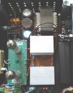
I recently completed this 12B4 preamp and was very happy with the result, except that there was a very faint hum on the speakers. This morning I was committed to find and solve the cause.
Took out the scope and start probing around. Found nothing. 🙁
Disconnect all ground wires and tried EVERY possible arrangement. No improvement. 🙁
Then, by pure luck, while cables was hanging everywhere connected with crock leads, I moved the ground lead just slightly to a different position (still connected on both sides) and suddenly the hum was gone on the 1 speaker.
Basically I now "created" a new "ground loop" with 2x 20cm long ground leads, from the output ground back to the star ground, but routed along the one side of the HT transformer. In that, and only that exact routing position, all hum is gone. 😀
It looks like crap, but sounds amazing. 😉
Attachments
Last edited:
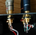
Although I did use insulated RCA sockets, it is quite possible that there can be some bad insulation taking place. I did notice that the insulation washers were supposed to have a small shoulder, fitting inside the chassis hole, but there were no shoulders on these. So they can move and cause a possible short on the edge. 😕
They were cheap eBay specials.
Will have a look tomorrow.
(Yes, not ideal but only had a 50k POT, padded it with 47k resistors. 😱 )
They were cheap eBay specials.
Will have a look tomorrow.
(Yes, not ideal but only had a 50k POT, padded it with 47k resistors. 😱 )
Attachments
Last edited:
I am already using this "ground breaker" scheme, which helped a lot.
Would you fit this magnetic choke (Schurter DENO) in series with that or where exactly?
I use these on all my audio projects:
5500.2042 Schurter Inc. | Filters | DigiKey
Would you fit this magnetic choke (Schurter DENO) in series with that or where exactly?
I use these on all my audio projects:
5500.2042 Schurter Inc. | Filters | DigiKey
Attachments
Last edited:
Between chassis and incoming ground wire from AC cord. It stops loops through safety ground to other equipment. Then connect your R/C/D/D to chassis.
You can cut the loop inserting a 10 ohm 1 w resistor between ac ground and chassis
It works fine
But in this case seems to be another issue
Walter
It works fine
But in this case seems to be another issue
Walter
You can cut the loop inserting a 10 ohm 1 w resistor between ac ground and chassis
It works fine
But in this case seems to be another issue
Walter
That sacrafices safety. The DENO does not.
Separate dirty and clean currents through different wires to capacitors of PS filters, and no need to invent "hum-bucking" bicycles.
BTW JDev, where did you purchase that print where the tubes are mounted?
eBay: Universal-Prototyping-PCB-for-tube-amplifier-7-pin-and-9-pin-Ceramic-tube-socket
Separate dirty and clean currents through different wires to capacitors of PS filters, and no need to invent "hum-bucking" bicycles.
Can you please explain to me how to do this.
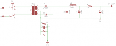
I have it connected exactly as on the schematic in post#5
Can this hum maybe generated by the cheap transformer?
First of all, you have a rectifier and a filter capacitor. The rectifier charges the capacitor each 1/120 of a second. Charging pulses are sharp, and currents that flow through wires that charge the cap are many times higher than what flows from the capacitor to the amplifier. If say the cap is being charged in 1/20 of the cycle (and you want as shorter as possible, for lower ripples), that means 28 times higher current peaks!
Each wire has own resistance, and even if it is very small, such pulses create on it voltage drops proportional to currents that flow through them.
So, the conclusion is, keep currents in their loops, so voltage drops on wires don't add to each other.
Use wires from transformer & rectifier to the first filter cap only and only for charging currents!
Take voltage directly from the cap, despite as if the same ground presents at the leads of a rectifier and of the cap. It is not the same! It is a wire between them! And voltage drops on that wire!
Then you probably have a choke, or a resistor, and the second cap? If you power your amp from the second cap, it's "-" lead is "the ground"! Not other wire, no matter how thick it is, connected to this lead!
Think of wires as of resistors with very small resistance. Any "ground bus" is only a distributed resistor. Draw your schematics with real "ground" wires, and replace them with resistors, to see what is going on.
But you are talking about noise. If he has a ground loop that is seperate issue.
Don't confuse him please.
Ground loop is just a ground loop, absolutely inert and silent, it causes absolutely no problems until somebody passes through it dirty currents. How? The same way I described above.
In the "Ground loop" there is is a word "loop" You need to cut this loop so the common mode current doesn't flow and no voltage (related with ac freq x 2) comes up.
I think if you power off the stuff the hum disappaer immediately.
One other method is to put a resistor of 10 ohm 1 watt in series on each neg rail of the channel to the star point ( if exist).
If the loop is in that point you can resolve.
Walter
I think if you power off the stuff the hum disappaer immediately.
One other method is to put a resistor of 10 ohm 1 watt in series on each neg rail of the channel to the star point ( if exist).
If the loop is in that point you can resolve.
Walter
Thank you for all advice.
Today I tried all the suggestions and theories, none made any difference at all.
The only way so far to reduce the hum, was as described in my 1st post, by routing the 2 output grounds along the side of the mains transformer. If I just move them slightly to a different position, I can hear the hum increasing.
It is if the magnetic field around the transformer cancels the hum in the ground cables (I don't know how that works)
I read somewhere that a poor quality transformer can also cause this hum (not the mechanical kind of hum)
I am looking at another transformer - R-core.
If it is not that, at least I have a transformer for another project. 😉
If you have a doubt on trafo, you can (for test) put it out of the box with the some jumper on cables.
In every case each channel, without any connection in input and output and the power supply, must be isolated from ground ( chassis).
The single negative wire of each channel goes at star point where one cable from power supply is connected (+ one for filaments ).
The pin jack must be isolated
Walter
- Status
- Not open for further replies.
- Home
- Amplifiers
- Tubes / Valves
- Hum - groundloop solution