I need to get +/-15v 300mA max varying / non-symmetric load currents on both +/-.
No need for high precision though.
There is only a single 40v 1amp available inside the box.
I first thought about just using a pair of 7815/7915 but don't think it would work now ... or does it ?
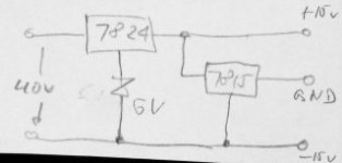
The only other idea I have so far is to first regulate to 30v and then split via zeners.
Will #1 and/or #2 work ?
Are there alternatives ?
No need for high precision though.
There is only a single 40v 1amp available inside the box.
I first thought about just using a pair of 7815/7915 but don't think it would work now ... or does it ?
The only other idea I have so far is to first regulate to 30v and then split via zeners.
Will #1 and/or #2 work ?
Are there alternatives ?
Attachments
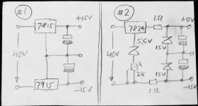
My concern with #1 is as follows:
what if I load the +15v rail but not the -15v (or much less)
there's no return path from the virtual ground to the actual power supply ... !?
what if I load the +15v rail but not the -15v (or much less)
there's no return path from the virtual ground to the actual power supply ... !?
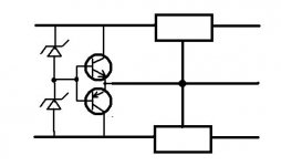
Through the npn (or pnp) transistors.
They (with the zeners) will put the ground point within a volt or two of half.
This will make sure each regulator has headroom independent of load imbalance.
I've used this type of circuit of dozens (yes, dozens) of times with a 30V isolated supply to get -4V and +26V supplies. It was only running a couple of instrumentation amplifiers so I did not need the transistors but the idea is the same.
In your case if there is a load imbalance there will be a shift in regulator supply potential. This is what the "line regulation" part of the regulator spec is for.
you cannot do this if u have sigle power supply....put two diodes one side cathode and anothr one anode on one terminal and use other terminal as gnd....and then regulate it....
I have been using this schematic with good result.
http://hem.bredband.net/hififorum/schema/Power.png
http://hem.bredband.net/hififorum/schema/Power.png
Last edited:
#2 will work, but will be touchy about the adjustment: you could easily fry the zeners, or end up with a "dead-band" of high impedance in your ground.Will #1 and/or #2 work ?
Are there alternatives ?
You could increase the 1 ohm resistors, but of course this will reduce the available current
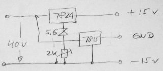
The circuit will fry the zeners if the 1A supply is not limited in some wayIf you are concerned about the regulation headroom on LM7x15 regulator take a look at this cct using 21-22V zeners.
This circuit is not properly compensated and will exhibit a huge impedance peak somewhere in the KHz range.I have been using this schematic with good result.
http://hem.bredband.net/hififorum/schema/Power.png
Depending on the amplifier and the 470µ's parameters, it could even oscillate under certain conditions.
2x TL431 for small loads, ok, but with 300 mA loads?Works like a champ
Originally Posted by DUG View Post #2
If you are concerned about the regulation headroom on LM7x15 regulator take a look at this cct using 21-22V zeners.
Originally Posted by Elvee View Post #8
The circuit will fry the zeners if the 1A supply is not limited in some way
A 21V zener (example DDZ21) has a tolerance of 20.64V to 21.71V at 5 mA of test current and is rated for 500mW.
At 20V the current will be less than the 5 mA of test current and therefore less than the 105mW that would be dissipated under test conditions.
I don't believe they will fry at 20% of rating.
The way to do this is to use a couple of switching regulators, one configured in the inverting mode. Even here you will have to be careful about the chips you employ and you may have to drop some voltage with a zener. See the constraints in the article below.
Making a Voltage Inverter from a Buck (Step-Down) DC-DC Converter - Application Note - Maxim
Circuits with virtual grounds are rarely very effective and the lower the impedance you want in the ground rail the greater the inefficiency.
Making a Voltage Inverter from a Buck (Step-Down) DC-DC Converter - Application Note - Maxim
Circuits with virtual grounds are rarely very effective and the lower the impedance you want in the ground rail the greater the inefficiency.
Even with high accuracy zeners like your example, it will still be highly risky and inconvenient: in your calculation, you assume an perfect accuracy on the 40V; this will not generally be the case.Originally Posted by Elvee View Post #8
The circuit will fry the zeners if the 1A supply is not limited in some way
A 21V zener (example DDZ21) has a tolerance of 20.64V to 21.71V at 5 mA of test current and is rated for 500mW.
At 20V the current will be less than the 5 mA of test current and therefore less than the 105mW that would be dissipated under test conditions.
I don't believe they will fry at 20% of rating.
Even with a perfect 40V supply and perfect 21V zeners, the ground thus created will have a high impedance "dead band" from 19V to 21V
This design is based on the information given: 40V
And it will work based on that.
I did not say it would work at 45V or 90V or 500V.
If the source was not 40V then it would have been stated as such.
I agree that at 42V there would be a problem with what I displayed.
If it would not have been 40V or would have been a "40V just rectified and filtered supply" then the design would have been different to allowed for it.
🙂
deadband:
What was not shown was capacitors on the regulated output. When they are used the ground will be as good as what it is connected to. Goodbye "deadband"
🙂
this thread may help
I considered something similar quite some time ago - discussed here http://www.diyaudio.com/forums/power-supplies/174791-virtual-ground-power-amp-applications.html
I whipped up the final circuit and it worked quite well, although I never put it to it's original intended purpose...
I considered something similar quite some time ago - discussed here http://www.diyaudio.com/forums/power-supplies/174791-virtual-ground-power-amp-applications.html
I whipped up the final circuit and it worked quite well, although I never put it to it's original intended purpose...
http://www.ti.com/lit/ds/symlink/tle2425.pdf
http://www.ti.com/lit/ds/sgls345/sgls345.pdf
If you need to drive more ground current then you just need to add a power buffer, like the BUF634, at the Virtual Gnd output of the TLE2425/6.
Or more simply, make your own potential divider using 2 matched resistors and us that as input to the BUF634.
Of course if you want +/-15V from 40V, you should regulate the 40V down to 30V first.
Then split using virtual ground circuits.
Patrick
The use of brute force to compensate for an abysmal shortfall of a circuit is rarely a good idea.deadband:
What was not shown was capacitors on the regulated output. When they are used the ground will be as good as what it is connected to. Goodbye "deadband"
🙂
In this case, a simplified version of the quad style V.G. is a better option: it does not require accurate components or supplies, it is self adapting, is not power-limited by the zeners, is self-centering and guarantees a maximum dead band of 1.2V in all cases.
Attachments
That cct will work as well.
It will be less tolerant on load imbalance but will be very tolerant of primary supply swings.
If the load imbalance is significant, one of the feed resistors could be shunted by a zener.
best of both ideas.
🙂
It will be less tolerant on load imbalance but will be very tolerant of primary supply swings.
If the load imbalance is significant, one of the feed resistors could be shunted by a zener.
best of both ideas.
🙂
In this case, a simplified version of the quad style V.G. is a better option: it does not require accurate components or supplies, it is self adapting, is not power-limited by the zeners, is self-centering and guarantees a maximum dead band of 1.2V in all cases.
I knew about the quad style V.G. and have actually used it successfully before.
In my case I would have to put a 40v -> 30v regulator in front of it. That would most likely work well enough.
Just for fun ... would any of these work as well ---> maybe the 15v reg runs a little hot ...
Attachments
No, for optimum performance, you should locate it before the two 15V regulators, DUG's style.In my case I would have to put a 40v -> 30v regulator in front of it. That would most likely work well enough....
Just for fun ... would any of these work as well ---> maybe the 15v reg runs a little hot
It could work on the condition the current consumption of the negative supply is always greater than the positive: regulators can only source current.
You could make sure it is the case by adding a bleeding resistor.
#1 in the original post will definitely not work.
Same with the last two.
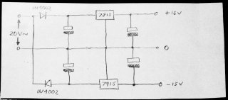
But I finally found my solution to the problem.
I overlooked that I do have AC voltage available.
With that I can build a voltage doubler followed by 7815 / 7915 regulator pair.
The fact that its only half wave rectified doesn't bother me.
Regulators will remove the ripple anyway.
Done.
Same with the last two.
But I finally found my solution to the problem.
I overlooked that I do have AC voltage available.
With that I can build a voltage doubler followed by 7815 / 7915 regulator pair.
The fact that its only half wave rectified doesn't bother me.
Regulators will remove the ripple anyway.
Done.
Attachments
- Status
- Not open for further replies.
- Home
- Amplifiers
- Power Supplies
- How to split single 40v into +/-15v ?