In another thread "My wave isn't square", there is some discussion about the amount of negative feedback applied in a tube amp circuit.
Showing my lack of amp theory: How does one measure (or calculate) the dB of negative feedback being applied in a circuit? Is it simply a matter of measuring AC voltages at output and feedback point and finding the ratio?
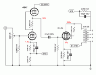
As an example, how would I proceed to measure dB of feedback in this circuit, which I recently built? (Schematic attached).
Thanks for your help!
Showing my lack of amp theory: How does one measure (or calculate) the dB of negative feedback being applied in a circuit? Is it simply a matter of measuring AC voltages at output and feedback point and finding the ratio?
As an example, how would I proceed to measure dB of feedback in this circuit, which I recently built? (Schematic attached).
Thanks for your help!
Attachments
The amount of feedback is roughly (open loop gain)/(closed loop gain), then expressed as dB. Open loop gain is calculated from the circuit diagram (or measured/simulated) with the feedback disconnected. Note that disconnected does not mean the feedback components are just removed, because they affect the circuit in other ways too.
For the circuit you give, to open the feedback loop you would need to break the NFB connection, and then connect the output side of that to a resistor which models the effect of 220R in parallel with the 6SN7 cathode, and connect the top of the 220R resistor (the other NFB connection) to ground via 4.7K and 100pF in parallel (strictly, with something in series to represent the OPT secondary impedance). In practice, this level of detail is often omitted and an approximate result obtained. Anyway, find the open loop gain A as a voltage ratio.
Then find the feedback fraction b (or beta). In your case it is roughly 220/4700 at mid-band frequencies, but you ought to take account of the 6SN7 cathode impedance too. Then closed loop gain = A/(1+Ab), but be careful about signs because if A is negative sometimes people write A/(Ab-1). If A is big enough then Ab is the amount of feedback.
I can't give a full explanation here. You need to read a good book on electronics or servo systems.
Thanks for a very clear explanation.
It's more complex than I thought- definitely not something I'll make a habit of measuring. It may be that the casual references about changing the feedback from say, 6dB to 20dB are coming from simulation calculations?
John
It's more complex than I thought- definitely not something I'll make a habit of measuring. It may be that the casual references about changing the feedback from say, 6dB to 20dB are coming from simulation calculations?
John
The amount of NFB is simply the amount by which the NFB reduces the open loop gain. So measure your amp's voltage gain in dB without feedback (disconnect it from the output transformer secondary) then measure the gain in dB with the feedback applied. The open loop gain in dB minus the closed loop gain in dB is the amount of feedback in dB.
Cheers
Ian
Cheers
Ian
Casual comments on an audio board could come from people who actually understand the complexities or people who don't realise that there are complexities.
The approximation given by ruffrecords (and me) will often be close enough for practical purposes.
The approximation given by ruffrecords (and me) will often be close enough for practical purposes.
Casual comments on an audio board could come from people who actually understand the complexities or people who don't realise that there are complexities.
The approximation given by ruffrecords (and me) will often be close enough for practical purposes.
I second that. DF96's explanation is about as short as it gets while still remaining accurate.
For the full explanation, I'd refer to college-level texts. Sedra/Smith, "Microelectronic Circuits" is my preference. If I recall correctly, Chapter 8 contains about 80~100 pages on stability.
~Tom
- Status
- Not open for further replies.