Can anyone point me to a thread that explains how to implement a LR 24db active crossover? I'm sure there must be one somewhere but my searches have come up empty. I don't know where to set the corner frequencies. I'm using Sigma Studio fwiw.
Thanks,
Shawn
Thanks,
Shawn
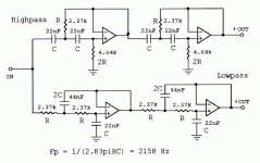
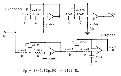
You can just take the example circuit and scale the resistor values for a different frequency.
If you want a lower frequency than 2158Hz, then increase all the resistor values by a factor of ( 2158 / f ).
If you want a lower frequency than 2158Hz, then increase all the resistor values by a factor of ( 2158 / f ).
Attachments
Last edited:
You might try looking at the miniDSP website. They have lots of well written tutorials. I know you have Sigma Studio but the concepts are the same.
Stereo 2 Way Xover
In either case, you need to measure the raw response. Use REW and then use the built in digital filters section in REW to apply filters and EQ onto your data. First apply gentle EQ cuts to reduce peaks but never gain to raise a dip. Get it as flat as possible. Overlay the textbook LR24 onto the plot with the XO frequency you want. Then apply the LR24 parameters to your data to get it to match. Once you have these simulated PEQs and LR24 parameters - transfer them to Sigma Studio. You could slowly tweak things in Sigma Studio and measure in real time. But it will take a lot of measurements and you will have a hard time getting a textbook LR24 by trial and error. If you had used miniDSP, REW actually can save all the simulated settings and then export that into the miniDSP programming app.
If you need help in how to set up connections in Sigma Studio, videos like this may be helpful:
[#17] ADAU 1701 + Sigma Studio Tutorial (WONDOM DSP) - YouTube
Last edited:
Hi XRK, nice time hear from you again.
I read that piece beforehand but was still left with the question of where to put low pass and high pass corner points so that they will sum flat. For instance I have a 10” woofer and 10” waveguide and thus want a crossover around 1350hz.
I read that piece beforehand but was still left with the question of where to put low pass and high pass corner points so that they will sum flat. For instance I have a 10” woofer and 10” waveguide and thus want a crossover around 1350hz.
Last edited:
You do have measurements of both drivers in-box and on-baffle?
A simulation in VituixCAD will tell you everything you need to know about the XO. I highly doubt they will be pure 24dB/octave LR filters, life is usually much more complicated.
A simulation in VituixCAD will tell you everything you need to know about the XO. I highly doubt they will be pure 24dB/octave LR filters, life is usually much more complicated.
I should explain that my own background is mathematical:
This sort of LR4 filter can sound quite reasonable:
You get what you get. Steep filters incur severe time delay. But lower distortion.
This excellent Scanspeak plus Ribbon speaker built by my good friend Rick Craig of Selah Audio:
What I am saying is there is a bit more to it than simply algebraic LR4 theory. Time alignment and dispersion plays a part.
AFAIK, even Troels Gravesen, who has been known to do the odd active crossover, would still first get a driver reasonably flat before electronically filtering it:
DIY-Loudspeakers.
Hope it helps.
Okay thanks. I haven’t measured them yet, I was just kinda wanting to play around blind a little, the speakers have passive xo right now but it’s high at 2k. They are PA speakers so likely protection for tweeter at high level. It’s a celestion neo CD and celestion’s measurements say it’s flat down to 1K. So I just wanted to play around a little to see.
Sounds like I should maybe measure them, I just didn’t want to move the speakers around. The receiver has audyssey and with the simple 2nd order passive filter they sound great.
Sounds like I should maybe measure them, I just didn’t want to move the speakers around. The receiver has audyssey and with the simple 2nd order passive filter they sound great.
Setting up LR4 active
i opened thread about active LR4 cause i wanted to know how it should look like when measured.
it might be easier to set up with direct radiating drivers but using wavequides or horns things seems to change.
i opened thread about active LR4 cause i wanted to know how it should look like when measured.
it might be easier to set up with direct radiating drivers but using wavequides or horns things seems to change.
Okay thanks. I haven’t measured them yet, I was just kinda wanting to play around blind a little, the speakers have passive xo right now but it’s high at 2k. They are PA speakers so likely protection for tweeter at high level. It’s a celestion neo CD and celestion’s measurements say it’s flat down to 1K. So I just wanted to play around a little to see.
Sounds like I should maybe measure them, I just didn’t want to move the speakers around. The receiver has audyssey and with the simple 2nd order passive filter they sound great.
Just because a compression driver is flat down to 1kHz, it doesn't necessarily mean it'll be low distortion down there. It'll also depend on the HF horn etc - best to do some measurements to find out what's what.
Chris
what hardware/software are you using to execute your digital filter? The software will determine the details of how you implement.
For example, Hypex Filter Design (HFD) software is very different than MiniDSP... yet both could achieve the exact same driver EQ and LR4 filter results.
For example, Hypex Filter Design (HFD) software is very different than MiniDSP... yet both could achieve the exact same driver EQ and LR4 filter results.
Chris - It's a Celestion CDX1 1425. They say it's 2k - 20k with a 2.5k - 12db per octave recommended crossover. It came in a pair of Yorkville YX10 which cross at 2k to a 10" driver.
I was curious to see what would happen if I went lower to better match directivity. I'm in an apartment so I never listen loud, rarely over 60db. It's in a 10" waveguide that has a similar looking profile to a SEOS when put next to each other. It sounds quite nice considering I got the speakers for $100 in great condition. They were used in a church rec room a few times a month. I took the metal grills off, sealed the ports, put some pink stuffing in them, and bypassed the XLR for regular wire.
I know how to measure freq resp but I'm not familiar yet with measuring distortion... does REW automatically do that when you run a sweep? I can't remember.
Jim - I'm using an ADAU1452 board with 5V linear power supply between an AV receiver and multi channel class AB amp. I also have a miniDSP nanoAVR HD on the front end between source and receiver. I have DSP coming out the wazoo. I use sigma studio for the ADAU1452.
For the curious minds, I got the nanoAVR first and then realized if I wanted to keep the dynamic loudness eq via Audyssey that I would need the active XO in between pre out and amp. So I got the ADAU1452.
Playing with these Yorkvilles is practice for a 12" SEOS based project that's in the works.
Last edited:
Just remember that you want the electro-acoustic (filter + driver response) to follow the LR4 response curve. Using DSP I know of two methods (both require measurements) to achieve this:
1. What I jokingly call the “hammer” method: Use the DSP to EQ (i.e. hammer) the response of each driver flat 1-2 octaves on either side of the crossover frequency. Then a textbook LR4 filter is applied to each driver. Finally, add a tweeter delay to align it with the woofer at the crossover frequency. You still have to be aware of the drivers’ limitations and not over extend the drivers’ capabilities when EQ’ing them flat. Grimm Audio has a nice write up HERE.
2. Design to a target response: Modify the driver’s frequency response and “massage” it to match the LR4 filter response. Then add a tweeter delay to align it with the woofer at the crossover frequency. This is very similar to designing a passive crossover, except when using DSP you have more options (i.e. gain/boost) to massage the driver’s response.
Since you’re using SigmaStudio you can implement either method using the “Auto EQ” control:
To implement the hammer method you set the “Target Response” to a flat response and limit the range 1-2 octaves either side of the crossover frequency. The control will then automatically calculate the biquads to flatten the response. Then you use the crossover tab to select a LR4 filter. To complete the design add a delay block to the tweeter output after the Auto EQ block. Temporarily flip the tweeter polarity (either physically or by using a SigmaStudio control) and adjust the tweeter delay until you measure a deep null. Then change the tweeter polarity back to normal.
To design to a target response you select the “Target from Filters” option in the “Target Response” tab. From there you can select the target filter response to match. Unfortunately, the LR4 filter response isn’t in the list. So you need to select two Butterworth filters at the same crossover frequency (two high pass filters for the tweeter and two low pass filters for the woofer). This gives the same target response as a LR4 filter. In this case you don’t use the crossover tab, but you still need to do the same tweeter delay routine.
The AutoEQ control does have several idiosyncrasies and outright bugs that have to be dealt with. I attached a copy of the AutoEQ Wiki updated with my color coded comments about the problems and how to work around them. Hopefully this will help you out. YMMV.
Attachments
Last edited:
Thank you! I appreciate the instructions. Sigma Studio doesn't ask where I want the crossover for LR4 though, it just asks me where I want the corner frequencies. I'm not sure how far on each side I should have them from the desired XO point.
Just remember that you want the electro-acoustic (filter + driver response) to follow the LR4 response curve. Using DSP I know of two methods (both require measurements) to achieve this:
1. What I jokingly call the “hammer” method: Use the DSP to EQ (i.e. hammer) the response of each driver flat 1-2 octaves on either side of the crossover frequency. Then a textbook LR4 filter is applied to each driver. Finally, add a tweeter delay to align it with the woofer at the crossover frequency. You still have to be aware of the drivers’ limitations and not over extend the drivers’ capabilities when EQ’ing them flat. Grimm Audio has a nice write up HERE.
2. Design to a target response: Modify the driver’s frequency response and “massage” it to match the LR4 filter response. Then add a tweeter delay to align it with the woofer at the crossover frequency. This is very similar to designing a passive crossover, except when using DSP you have more options (i.e. gain/boost) to massage the driver’s response.
Nicely stated, the two approaches 🙂
What's really cool i think, is how they both give identical final electrical filter results, when for the exact same acoustic output target.
I mean, they have to, if the final acoustic output is the same.
Just comes down to which method one finds easier, imo.
Personally, I find flattening to a straight line much easier than massaging to a curve. And I almost always end with less ripple in the xover region by flattening first.
I've done it both ways a lot, but nowadays i'll massage only when I have an insufficient dsp filter capacity to do both in-band and out-of-band flattening, in which case in-band usually gets first dibbs.
I agree the flattening approach is easier. Another AutoEQ control limitation I should mention is only Linkwitz-Riley filters (6/12/24/48 dB/oct) are available in the Crossover tab, so you're limited to those if using the flattening method. On the other hand, I was able to implement a Harsch crossover using the massage method. It took considerably more work, but was fun to do.
Would you happen to know a work around for this phase issue?.
In Sigma Studio, "the Bessel/Butterworth/Chebyshev/Linkwitz-Riley filters are all based on the Bilinear Transform. So the phase linearity of the analog prototype is not preserved after the transformation due to frequency warping."
In Sigma Studio, "the Bessel/Butterworth/Chebyshev/Linkwitz-Riley filters are all based on the Bilinear Transform. So the phase linearity of the analog prototype is not preserved after the transformation due to frequency warping."
Would you happen to know a work around for this phase issue?.
In Sigma Studio, "the Bessel/Butterworth/Chebyshev/Linkwitz-Riley filters are all based on the Bilinear Transform. So the phase linearity of the analog prototype is not preserved after the transformation due to frequency warping."
There is no true workaround other than FIR, used as linear phase.
It's why the best bet is to stay with as low an order that works, or play with milder phase changing Chebyshev or Harsch or something.....
...whatever works to keep phase wraps and group delay down.
- Home
- Loudspeakers
- Multi-Way
- How to LR 24db active crossover