This happened to me today. I applied amplifier AC output voltage, like +/-20V, to line input by mistake.
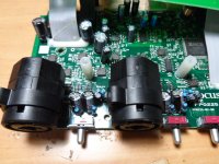
Soundcard inputs go through big electrolytic caps, then are clamped with schottkys to audio +/-5V rails. No series resistors are used. Then signal goes to IN+ of NJM2122 and 74HC4066 switches. Then there is a stage with NJM4565.
74HC4066 failed shorted. It is fed from audio +/-5V. These rails were only measuring 3V. Removing 74HC4066 allowed the rails to come up back. NJM2122 and NJM4565 seem to be OK.
However, there was no audio input or output in any channel. Audio codec CS4272 is fed from same +5V audio rail. There are no zeners for clamping audio rails. Codec failed too.
Continuing tracing the problem I checked serial interface of audio codec. Clocks are OK. Serial input is OK. I can get signal at computer side by briefly shorting serial input to serial output. The chipset does not seem to be damaged.
Time to order some parts.
It's a shame that neither series resistors nor zeners are included. Input protection is cosmetic. The codec chip is only rated +6V abs. max. It has a sticker that says "will fail if input is overloaded".
Curious about the input signal path. The THD on the 74HC4066 analog switch is listed at around 0.04%, but the Scarlett 2i2 line input spec is much better at THD+N <0.003%. Is the switch not directly in the signal path?
How much is your time worth to troubleshoot and repair it?
You can get a new one for $150.00. 🙂
If I thought I was going to spend more than a couple of hours on it, I would probably round file it. 🙂
Dave.
You can get a new one for $150.00. 🙂
If I thought I was going to spend more than a couple of hours on it, I would probably round file it. 🙂
Dave.
Expending $150 in a new one leaves a type of mark in the brain. Fixing it leaves another type of mark in the brain.
DC3: The THD of 4066 depends on voltage swing and current through switch. There are tricks.
DC3: The THD of 4066 depends on voltage swing and current through switch. There are tricks.
There is of course a 3rd way, which is to come up with a protection circuit that all of us using cheap sound cards and USB modules can use. That way you upgrade your scarlet to pro levels of beatings proof and stop the rest of us suffering the same fate when we do something daft (which we all will).
Autoranger designed by Jan Didden does exactly this - protects the sound card. I have Scarlett 2i2 and Autoranger and thus can sleep well🙂
I'm curious because I've got a similar soundcard (18i8). Focusrite claims +22dBu max input for the line inputs of the 2i2 (or 9.75vrms - 27.6vpp). How do they achieve that from +/-5V supply if there isn't a divider at the input ?
Thx for the info btw.
edit: @ billshurv : the whole reason for this too: 40W/8R not so dummy load for amplifier testing
Thx for the info btw.
edit: @ billshurv : the whole reason for this too: 40W/8R not so dummy load for amplifier testing
Parts arrived.
- CS4272 (TSSOP-28)
- 74HC4066 (SOIC-14)
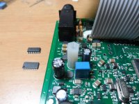
I replaced the parts. The TSSOP is easy to solder without special gear (only fine iron and round hot air nozzle), even in a 4 layer PCB with ground planes under the IC, provided that some solder/flux is applied both to IC leads and PCB pads, then hot air never fails.
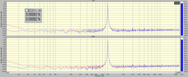
A quick loopback THD measurement proved both channels in/out to be in good condition.
I added two 5.1V zeners in parallel with the output capacitors of +/-5V PSU. Calculated zener impedance in the 50mA to 100mA range is 12 ohm. Calculated sinking at 6V is 75mA, plus another ~25mA from op-amps, etc. (Picture attached.)
I added 100ohm series resistors to signal inputs (8 in total), by shaping them adequately and soldering them in series with input AC coupling electrolytics. The average drop needed across these resistors to provide the 100mA required to elevate the +5V rail (also used by CS4272) above +6V (CS4272 abs. max. analog Vcc) is 10V, plus the 6V of the rail itself, plus the 47uF electrolytic allowing 2.1V more each 1ms, or the 10uF allowing 10V more each 1ms (until something blows, now the CS4272 has far less chances). (Picture attached, also sowing replaced ICs.)
I did a final THD loopbcack testing, it goes to 0.001%, so it is OK for measuring THD. (Picture attached.)
- CS4272 (TSSOP-28)
- 74HC4066 (SOIC-14)
I replaced the parts. The TSSOP is easy to solder without special gear (only fine iron and round hot air nozzle), even in a 4 layer PCB with ground planes under the IC, provided that some solder/flux is applied both to IC leads and PCB pads, then hot air never fails.
A quick loopback THD measurement proved both channels in/out to be in good condition.
I added two 5.1V zeners in parallel with the output capacitors of +/-5V PSU. Calculated zener impedance in the 50mA to 100mA range is 12 ohm. Calculated sinking at 6V is 75mA, plus another ~25mA from op-amps, etc. (Picture attached.)
I added 100ohm series resistors to signal inputs (8 in total), by shaping them adequately and soldering them in series with input AC coupling electrolytics. The average drop needed across these resistors to provide the 100mA required to elevate the +5V rail (also used by CS4272) above +6V (CS4272 abs. max. analog Vcc) is 10V, plus the 6V of the rail itself, plus the 47uF electrolytic allowing 2.1V more each 1ms, or the 10uF allowing 10V more each 1ms (until something blows, now the CS4272 has far less chances). (Picture attached, also sowing replaced ICs.)
I did a final THD loopbcack testing, it goes to 0.001%, so it is OK for measuring THD. (Picture attached.)
Attachments
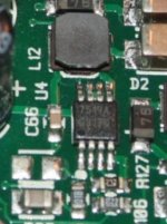
Hello. I bought a Scarlett2i2, 1Gen broken. An HC 4066 was burned. Because of this I lost +/- 5V voltages. Unfortunately someone tried to repair it and he removed U4 I.C. Does anyone know what model this I.C.
Thank you very much for your help!

Thank you very much for your help!
It's a shame that neither series resistors nor zeners are included. Input protection is cosmetic. The codec chip is only rated +6V abs. max. It has a sticker that says "will fail if input is overloaded".
Series resistors would raise the noise-floor, remember these are also microphone inputs. The lesson is you need to provide your own attenuator/protection circuitry for high power signals.
In other words a dummy load / attenuator unit is what you need to measure power amps using a microphone-capable input section.
Hello. I bought a Scarlett2i2, 1Gen broken. An HC 4066 was burned. Because of this I lost +/- 5V voltages. Unfortunately someone tried to repair it and he removed U4 I.C. Does anyone know what model this I.C.
Thank you very much for your help!
7519a (or ISL97519A) pwm stepup regulator.
Attachments
- Home
- Source & Line
- Digital Line Level
- How to kill a Focustire Scarlet 2i2