I would like to explain you all a new (as far I have read) concept for an output stage which I have been thinking for a while.
The basics of the idea are:
1)The transistors that drive the output current are never shut off. (In order to avoid distortions)
2)The bias point must be lower than the one in a class A biasing. (In order to increase efficiency)
3)A push-pull class AB configuration is not allowed
My solution for that approach (within a conceptual idea and every element is ideal) is to process not-linearly the signal before it is driven by the power section of the output stage. It means, to fit the input signal in a power transistor, inasmuch as the bias point of which cannot offer a whole linear cycle amplification.
Up to now what we achieve is just an asymmetric amplified signal. So in order to correct this non-linearity I thought to counteract it adding a new power inverted signal (that comes from the original input signal and it is amplified in a non-linear way as well), the result of the addition is a signal linearly amplified.
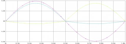
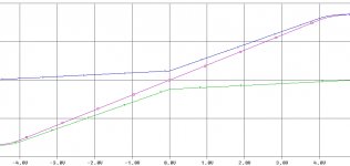
I leave some images generated with Pspice trying to make the idea clearer. The first one contains the voltage inputs (green and blue) and the voltage output (purple), the second one contains the hypothetic currents through the power transistors (blue and green) and the load (purple).


I attempted to implement this idea in Pspice with no success. The graphics you can see come from a conceptual schematic.
The point is: do you know any approach or clue which could make this possible? I am not referring to how to process the previous signal, just how to “add” the power signals (I tried with bridge configurations and the most extravagant ideas ever, without success neither )
)
Thanks 🙂
The basics of the idea are:
1)The transistors that drive the output current are never shut off. (In order to avoid distortions)
2)The bias point must be lower than the one in a class A biasing. (In order to increase efficiency)
3)A push-pull class AB configuration is not allowed
My solution for that approach (within a conceptual idea and every element is ideal) is to process not-linearly the signal before it is driven by the power section of the output stage. It means, to fit the input signal in a power transistor, inasmuch as the bias point of which cannot offer a whole linear cycle amplification.
Up to now what we achieve is just an asymmetric amplified signal. So in order to correct this non-linearity I thought to counteract it adding a new power inverted signal (that comes from the original input signal and it is amplified in a non-linear way as well), the result of the addition is a signal linearly amplified.
I leave some images generated with Pspice trying to make the idea clearer. The first one contains the voltage inputs (green and blue) and the voltage output (purple), the second one contains the hypothetic currents through the power transistors (blue and green) and the load (purple).


I attempted to implement this idea in Pspice with no success. The graphics you can see come from a conceptual schematic.
The point is: do you know any approach or clue which could make this possible? I am not referring to how to process the previous signal, just how to “add” the power signals (I tried with bridge configurations and the most extravagant ideas ever, without success neither
 )
)Thanks 🙂