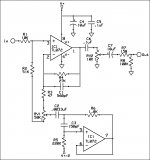
This is a treble boost that uses a gyrator circuit. I understand the gyrator circuit but can't quite figure the gain for IC2A. I see the feedback resistor R4 of 27K. So when the boost circuit is turned fully counter clockwise (towards RV1 pin 1 I believe) there will be no boost. And when turned fully clockwise, the boost is full. So what parts create the gain and how do I adjust them? What I really want is to decrease the overall gain. Hope I'm not too confusing 😀


The more I look at this, the less confident I am that the assumptions I'd like to make to give a quick, approximate analysis are reasonable. However...
The gyrator, plus C2 mimic an LCR series resonant circuit, impedance lowest at resonance, rising away from that.
Feeling a bit lazy, so Jack Orman's gyrator calculator gives Fres = 11.37 kHz, Q = 2.36. The resistance to ground, from the wiper of RV1, at resonance, should be that of R6, ie 1k8.
This resonant impedance, 1k8, is much less than that of R2 and RV1, so with the wiper full ccw to pin 1, the gain, at resonance might be of the order of
Gres= (51k/(51k+10k)) x (50k+47R+27k)/(50k+47R)
If it weren't for C1, 560pF; at 11.37 kHz this has a reactance of about 25k
Approximating further, guessing effective value of 27k // 560pF at 11.37kHz.....I know, this is unravelling fast...
Gres = (51k/(51k+10k)) x (50k+47R+17k)/(50k+47R)
which I make to be about 1.12
But this is just a bodge of the gain at resonance of the gyrator.
Unfortunately, it appears not possible to calculate the gain away from resonance by disconnecting the gyrator from the wiper of the pot in the way that it is in a typical graphic EQ circuit.
Some things do make spice nice....
- Status
- Not open for further replies.