Hi,
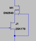
For the life of me, I can't figure this out. To protect jfets from high voltage, I like to use a depletion mode MOSFET as shown in the pic. The DN2540 being a 400V part, makes it safe beyond 60v of the 2SK170 while maintaining just 2V or so across the jfet.
As there is no such thing as a P-channel depletion mode MOSFET, how can I do the same for a lower half? A 2SJ74 is only safe to 50V or so.
Attachments
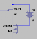
Use an enhancement P-MOSFET for the cascode, connect the gate to the P-JFET source with a voltage source (resistor, zener, voltage reference) of your choice, and a current sink connected between the MOSFET gate and the negative supply rail.
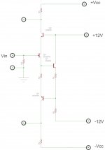
Or, you could connect the base of an NPN to the P-JFET source, connect a voltage source (resistor, zener, voltage reference) of your choice between the NPN emitter and P-MOS gate, again with a current sink connected between the MOSFET gate and the negative supply rail.
In either case, using a noise-absorbing capacitor across the voltage source may result in better performance.
Component count may be higher than what you would like, but enhancement PMOS cascode are straightforward and will work.
hth, jonathan carr
If you use a separate N-device as a cascode driver, what will load the P-JFET source will be the N's base/gate, which will sharply reduce any current loading at the P-JFET source (compared to the Vref by itself).
For the cascode driver I'd first try a high-beta NPN, and if I needed to further reduce the effects of base currents, I'd next try a Darlington, then a small N-MOSFET.
hth, jonathan carr
For the cascode driver I'd first try a high-beta NPN, and if I needed to further reduce the effects of base currents, I'd next try a Darlington, then a small N-MOSFET.
hth, jonathan carr
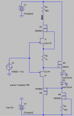
The circuit looks plausible, although it eludes me why you have 500 ohms at the MOSFET drain on the positive side and not the negative.
In any case, feel free to keep us informed.
cheers, jonathan carr
In any case, feel free to keep us informed.
cheers, jonathan carr
mosfets are not the best devcies for the cascodes - poor gm, parasitic C compared to properly sized bjt
biasing the bjt can be more challenging
if you want to stretch your understanding of what you could accomplish with subtle varions on cascode you shoud read http://www.essex.ac.uk/csee/research/audio_lab/malcolmspubdocs/J10 Enhanced cascode.pdf
Hawksford shows a 10x high frequency distortion improvement for the "correct" connection of the cascode, Nelson Pass also uses this variation
speaking of bias the 1KOhm shown in your post pretty much wastes the low noise fet low V noise while you still are dealing with the cost of the large area jfet die in high parasitic C
Last edited:
jcx: yes the 1k is wrong, but is there as a placeholder. Interesting paper, but I don't see how it applies here where I'm protecting low voltage jFETs for use on much higher supply rails. The question I'm trying to answer is, how can I use a 25V 2SJ74 on a 150V rail and allow full common-mode voltage swing.
jcarr: the 500 is the I-to-V converter where it goes to the next stage
jcarr: the 500 is the I-to-V converter where it goes to the next stage
 )
)
- Status
- Not open for further replies.
- Home
- Amplifiers
- Solid State
- How to do floating cascode on the P-channel side?