Can anybody help me figure out how to convert a tube amp that uses 2 6V6's convert to use 6CA7's or EL34's or 6L6's
The voltages are going to be low for any of those tubes coming from a 6v6. Use a load line calculator to see if you are going to be better off stay with the 6v6.
Can anybody help me figure out how to convert a tube amp that uses 2 6V6's convert to use 6CA7's or EL34's or 6L6's
Your power transformer will have to accomodate the extra 1 to 2 amps of filament current as well. Make sure it can.
i will check the power transformer to make sure it can handle the 1 to 2 amp needed to run 6ca7,el34 or 6l6, i have a pair of 6ca7's and a pair of 6L6's do they draw the same amp's or are they diffrent? I also read that if you tie together pin 1 with pin 8 on tube socket for each output tube is all you had to do, is that a good idea or is there more to it then that? I have 2 old Dictograph mono amp's from the 50's that were converted to guitar amps(not by me) and both of them were using two 6V6 output tubes and I had one of the amps converted to use 6CA7's output tube and I really like how it sounds and how much more punch you get from having more watts witch is nice cuz i don't have to turn that amp up as much to get what im looking for, and the guy who did the mod on that amp is no longer with us and i am now wanting to convert my other dictogragh amp to use 6CA7's or EL34's or 6L6's to kind of match to punch of the other dictogragh i had converted, there might be a penciled schmatic on the back of the bottom cover i will check that and if there is one i will post it,but i have been running the convered amp with 6CA7's for over a year now and just replaced the 6CA7's with EL34's it still sounds great just want do the same thing to the other one! and anybody that helps me out I can't thank you enough!
i will check the power transformer to make sure it can handle the 1 to 2 amp needed to run 6ca7,el34 or 6l6, i have a pair of 6ca7's and a pair of 6L6's do they draw the same amp's or are they diffrent? I also read that if you tie together pin 1 with pin 8 on tube socket for each output tube is all you had to do, is that a good idea or is there more to it then that? I have 2 old Dictograph mono amp's from the 50's that were converted to guitar amps(not by me) and both of them were using two 6V6 output tubes and I had one of the amps converted to use 6CA7's output tube and I really like how it sounds and how much more punch you get from having more watts witch is nice cuz i don't have to turn that amp up as much to get what im looking for, and the guy who did the mod on that amp is no longer with us and i am now wanting to convert my other dictogragh amp to use 6CA7's or EL34's or 6L6's to kind of match to punch of the other dictogragh i had converted, there might be a penciled schmatic on the back of the bottom cover i will check that and if there is one i will post it,but i have been running the convered amp with 6CA7's for over a year now and just replaced the 6CA7's with EL34's it still sounds great just want do the same thing to the other one! and anybody that helps me out I can't thank you enough!
6V6's draw .45 amps, 6L6's draw .9 amps, and 6CA7/EL34's draw 1.5 amps. So quite a difference. Yes, you have to tie pins 1 and 8 together for the 6CA7/EL34. But you will also have to make other changes to the circuit for the tubes to operate properly and avoid a possible meltdown. Generally it wouldn't be a good idea--the output transformer is wrong for the other tubes, the voltages are too low, etc. But if you have a schematic for the other one it would be interesting to see what was changed to make it work.
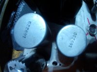
Did he change the output transformers too? Those two tubes require very different transformers, and if not then you would get less power from the 6CA7 just plugged into the 6V6 socket with minor modifications to accomodate it. The entire original conversion needs to be explained.I have 2 old Dictograph mono amp's from the 50's that were converted to guitar amps(not by me) and both of them were using two 6V6 output tubes and I had one of the amps converted to use 6CA7's output tube and I really like how it sounds and how much more punch you get from having more watts witch is nice cuz i don't have to turn that amp up as much to get what im looking for, and the guy who did the mod on that amp is no longer with us

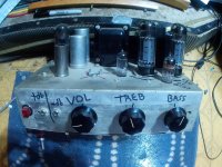
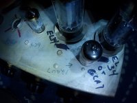
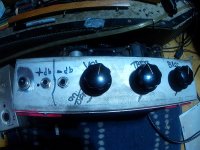
Ok I will try my best to explain what the 2 dictogragh amps were originally made, it looks like it had 4 preamp tubes a 12ax7,12at7,12au7, and 6C4 and the two 6V6's outputs and the one amp i had converted to use 6CA7 output tubes has only Vol,Treb,Bass so it looks like he took away 1 preamp tube(12at7)and that socket isn't used to get the amp's needed to run the 6CA7's, I'm going to open up both of them and take pics of everything i can i hope there's some kind of a schmatic, i will try to post all the pic's tonight. thank you to all who has been giving me info!
A lot of old tube amplifiers were made to run from 110V or 115V power mains.
1. Perhaps you have 117V, 120V, or 123V power mains, that stresses and heats old power transformers.
2. Then add the extra filament current from the secondary.
3. Then add the extra plate current from the B+ secondary to run the larger tubes, to get more power.
Wait a minute . . . How far are you from the nearest fire department, and how near are you to the nearest fire hydrant?
They took an old Buick engine and bored it out to 500 cubic inches.
It did not make it to the end of the 1/4 mile, because it blew up first.
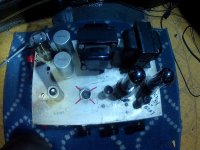
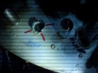
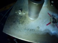
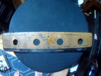
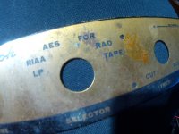
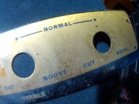
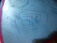
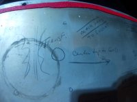
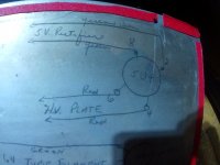
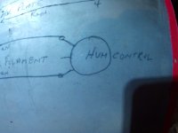
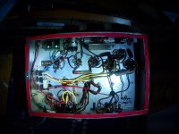
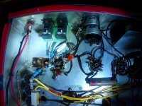
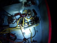
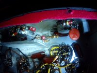
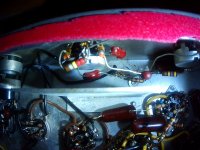
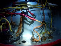
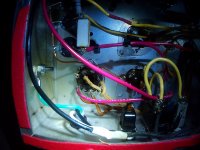
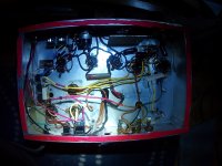
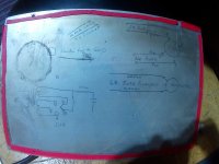
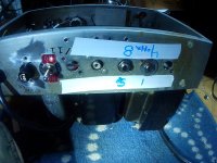
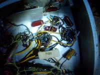
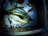
ok here are the pic's of both dictogragh amps ill only put pic's of the amp that was converted to run 6CA7 or EL34's in this post and the other amp ill put all the pics on my next post there is a schmatic ill put those pics on both post
Attachments
-
 SUNP0183.JPG581.3 KB · Views: 100
 -
 SUNP0184.JPG671.8 KB · Views: 93
 -
 SUNP0185.JPG401.5 KB · Views: 91
 -
 SUNP0186.JPG332 KB · Views: 83
 -
 SUNP0187.JPG377.5 KB · Views: 83
 -
 SUNP0188.JPG317.2 KB · Views: 83
 -
 SUNP0189.JPG553.4 KB · Views: 82
 -
 SUNP0190.JPG502.1 KB · Views: 94
 -
 SUNP0192.JPG617.3 KB · Views: 80
 -
 SUNP0193.JPG530.2 KB · Views: 72
 -
 SUNP0194.JPG416.6 KB · Views: 67
 -
 SUNP0195.JPG407 KB · Views: 87
 -
 SUNP0212.JPG464.7 KB · Views: 73
 -
 SUNP0213.JPG399.4 KB · Views: 81
 -
 SUNP0214.JPG403.3 KB · Views: 75
 -
 SUNP0215.JPG472.1 KB · Views: 80
 -
 SUNP0216.JPG396.6 KB · Views: 81
 -
 SUNP0217.JPG408 KB · Views: 89
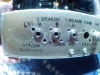
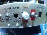
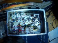
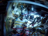
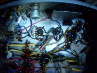
Okay, so one thing the modifier did was to relabel the speaker outputs for EL34s to reflect a lower load on the output tubes. Still doesn't answer a lot of questions. Can you send pics of the underneath of both amps? There must be some further modifications to the circuit.
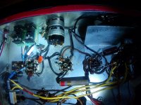
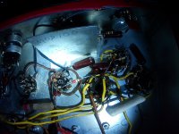
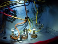
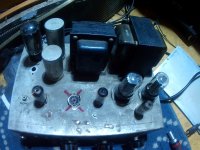
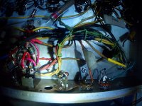
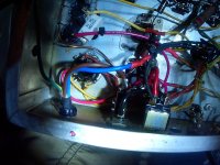
heres the other pics of the amp that still runs 6v6's i hope that helps cuz i don't enough about how write a schmatic or enough about how tube amp work but i would sure like to know everything there is to know about tube amps then i could do all the fixing or mods myself! the rest of the pics on the next post
Attachments
-
 SUNP0196.JPG403.5 KB · Views: 65
 -
 SUNP0197.JPG536.3 KB · Views: 63
 -
 SUNP0198.JPG529 KB · Views: 59
 -
 SUNP0199.JPG439.5 KB · Views: 55
 -
 SUNP0200.JPG432 KB · Views: 69
 -
 SUNP0201.JPG394.2 KB · Views: 68
 -
 SUNP0202.JPG457.1 KB · Views: 60
 -
 SUNP0203.JPG464.6 KB · Views: 63
 -
 SUNP0204.JPG466.5 KB · Views: 52
 -
 SUNP0205.JPG514 KB · Views: 69
 -
 SUNP0206.JPG427.1 KB · Views: 73
 -
 SUNP0207.JPG427.7 KB · Views: 58
 -
 SUNP0207.JPG427.7 KB · Views: 64
 -
 SUNP0208.JPG487.4 KB · Views: 62
 -
 SUNP0209.JPG252.5 KB · Views: 52
 -
 SUNP0210.JPG445.8 KB · Views: 60
 -
 SUNP0211.JPG602 KB · Views: 63
 -
 SUNP0212.JPG464.7 KB · Views: 64
 -
 SUNP0213.JPG399.4 KB · Views: 62
 -
 SUNP0214.JPG403.3 KB · Views: 73
the rest of the pics
Attachments

why would you give me some tip on how to mod my amp then make a joke about it? i put some pics of both my amps and there was somewhat of a schmatic thats the best i can do for giving any kind of info about the amps, so if you have a good safe idea that would help me im all ears, and eye'sA lot of old tube amplifiers were made to run from 110V or 115V power mains.
1. Perhaps you have 117V, 120V, or 123V power mains, that stresses and heats old power transformers.
2. Then add the extra filament current from the secondary.
3. Then add the extra plate current from the B+ secondary to run the larger tubes, to get more power.
Wait a minute . . . How far are you from the nearest fire department, and how near are you to the nearest fire hydrant?
They took an old Buick engine and bored it out to 500 cubic inches.
It did not make it to the end of the 1/4 mile, because it blew up first.
i posted a lot of pics of both amps and there is somewhat of a schmatic have a lookCan you post a schematic of the amp in question?
jeff
i posted i lot of pics of both amps if you need more pics like close ups i can do thatOkay, so one thing the modifier did was to relabel the speaker outputs for EL34s to reflect a lower load on the output tubes. Still doesn't answer a lot of questions. Can you send pics of the underneath of both amps? There must be some further modifications to the circuit.
This amplifier is listed in the radiomuseum web site. It seems to be a generic mid-50 design for home Hi-Fi use, with beefy transformers. The conversion to 6L6 / EL34 is unlikely to give a significant power boost and it may even be detrimental and increase the distortion, but it will change the sound signature and this may be the desired outcome for a guitar amplifier. The conversion should really be performed after some design calculation, but due to the simplicity of the circuit you may try to do it empirically instead. I would start by making sure that the amplifier does indeed works correctly as stock 6V6, because according to your pictures it has not been restored in a professional way previously. Check the main fuse value, it should be 2A or so; it is best replaced with a new, good fuse. Connect the speaker and leave the amplifier on for an hour or two. Check for overheating/burning smell/noises and be ready turn off it immediately if you see a output tube turning red. Measure the voltage at 6V6 pin 8 (cathode). A hook type of voltmeter lead would be very useful to get a stable reading and avoid sticking your hands next to dangerous voltages.
Turn off the amplifier, discharge the capacitors, and measure the original cathode resistor value between 6V6 pin 8 and ground. This resistor is inexpensive but it may get damaged by the following empirical tests, so it is best to know the value beforehand. The cathode current is the cathode voltage divided by the cathode resistor. Take note of this value. Then replace the 5Y3 with 5U4 / GZ34, and the 6V6s with 6L6s. The original rectifier is a 5Y3, replacing it with 5U4 (as done in the modded amp) does increase the anode voltage supply and makes it more suited for the bigger output tubes. Main filter capacitors may need to be replaced as well to reliably work at the higher voltage. A variac would be useful to turn on the amplifier slowly, but it is not essential. Turn the amplifier on. If the fuse does not open immediately, it is a good sign already. Measure the voltage at pin 8 again. It should be in the same ballpark as before. If it is significantly different, take note of the value and turn off the amplifier. Move the voltmeter lead to the center tap of the power transformer primary to measure the supply voltage, turn on the amplifier briefly again and measure the value. You then need to calculate a new cathode resistor value to get the same cathode current as the original design. Look up a tutorial or ask here with the measured values. If you are satisfied of the results, do not leave the amplifier unattended! Check for overheating for the next 2 hours at least, and turn off the amplifier immediately if the power supply transformer becomes hot. You are increasing the electrical stress on vintage parts that may be already weakened, and there is a real danger of damaging one or more transformers.
Turn off the amplifier, discharge the capacitors, and measure the original cathode resistor value between 6V6 pin 8 and ground. This resistor is inexpensive but it may get damaged by the following empirical tests, so it is best to know the value beforehand. The cathode current is the cathode voltage divided by the cathode resistor. Take note of this value. Then replace the 5Y3 with 5U4 / GZ34, and the 6V6s with 6L6s. The original rectifier is a 5Y3, replacing it with 5U4 (as done in the modded amp) does increase the anode voltage supply and makes it more suited for the bigger output tubes. Main filter capacitors may need to be replaced as well to reliably work at the higher voltage. A variac would be useful to turn on the amplifier slowly, but it is not essential. Turn the amplifier on. If the fuse does not open immediately, it is a good sign already. Measure the voltage at pin 8 again. It should be in the same ballpark as before. If it is significantly different, take note of the value and turn off the amplifier. Move the voltmeter lead to the center tap of the power transformer primary to measure the supply voltage, turn on the amplifier briefly again and measure the value. You then need to calculate a new cathode resistor value to get the same cathode current as the original design. Look up a tutorial or ask here with the measured values. If you are satisfied of the results, do not leave the amplifier unattended! Check for overheating for the next 2 hours at least, and turn off the amplifier immediately if the power supply transformer becomes hot. You are increasing the electrical stress on vintage parts that may be already weakened, and there is a real danger of damaging one or more transformers.
The messy side of tube amps and the fact that they still work more or less by putting anything in it can be misleading.
Being a man of transistor devices, I've been had more than once.
You have to be methodical, take a lot of time to check the values, do some calculations, draw load lines.
Empirically, it will always work, but at best, not as it should and at worst, it burns, I had the bitter experience of it on a PP of 2E22 last year, 600€ in the trash.
ilovetubeampspete,
I am sorry, I did not make it clear.
I was not joking, and an amplifier that either burns out, or even catches fire is not a joke.
Trying to get more power out of a power transformer is a loosing battle.
Amplifiers in the 50s were built to a price point.
They were not built to be modified to get more power out.
They were not built to have extra filament current 0.9A or 1.5A versus the 6V6 0.5A.
They were built to have a certain B+ voltage and a certain load current; not a higher current.
Transformers are built to work with a fixed range of power mains.
Power mains voltages increased over the decades.
More voltage applied to the primary will heat up the transformer.
In like manner, you can not add a second motor to your electric vehicle to get more power, the extra load might cause the batteries to catch fire.
By the way, the number that represents Horsepower BHP, and the number that represents Torque in foot pounds has an unusual characteristic: Horsepower # @ 5,250 rpm = Foot Pound Torque # @ 5,250 rpm.
When does Degrees C = Degrees F (that happens Only at: -40 Degrees C, and -40 Degrees F).
- Home
- Amplifiers
- Tubes / Valves
- How to convert a 6V6 tube amp to use 6ca7 or EL34 or 6L6 tubes