Hi,
I want to add a current overload protection to a regulated high voltage power supply.
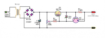
The design is somewhat similar to the schematic attached (but with zener stabilization), using a power MOSFET. The default output voltage is 600 VDC. The default current will be around 400 mA (fixed current, true class A amplifier).
How should I calculate the resistor value for the BC337 to get a current protection for 450 mA or 500 mA?
Regards, Gerrit
I want to add a current overload protection to a regulated high voltage power supply.
The design is somewhat similar to the schematic attached (but with zener stabilization), using a power MOSFET. The default output voltage is 600 VDC. The default current will be around 400 mA (fixed current, true class A amplifier).
How should I calculate the resistor value for the BC337 to get a current protection for 450 mA or 500 mA?
Regards, Gerrit
Attachments
Approximately 0.6/Ilimit, about 1.2V in your case (not hugely accurate but sufficient, since the knee is soft anyway).
Note that a protection resistor should be added in series with the base: 47 ohm for example (not critical at all)
Note that a protection resistor should be added in series with the base: 47 ohm for example (not critical at all)
Hi,
I want to add a current overload protection to a regulated high voltage power supply.
The design is somewhat similar to the schematic attached (but with zener stabilization), using a power MOSFET. The default output voltage is 600 VDC. The default current will be around 400 mA (fixed current, true class A amplifier).
How should I calculate the resistor value for the BC337 to get a current protection for 450 mA or 500 mA?
Regards, Gerrit
Hi Gerrit,
The base-emitter voltage on Q2 with 500mA through R2 shall allow a collector current in Q2 that is equal to the current flowing through R1 (current pinch-off).
My estimate is that R2 should be around 1 Ohm. BUT, with such a simple current limiter circuit it will be difficult to make sure that 400mA will not be limited while 500mA will be limited.
A circuit like that protect only for very short pulsed over current.Hi,
I want to add a current overload protection to a regulated high voltage power supply.
The design is somewhat similar to the schematic attached (but with zener stabilization), using a power MOSFET. The default output voltage is 600 VDC. The default current will be around 400 mA (fixed current, true class A amplifier).
How should I calculate the resistor value for the BC337 to get a current protection for 450 mA or 500 mA?
Regards, Gerrit
Longer periods will get the mosfet out of the safe operation zone.
To avoid such condition a foldback protection is needed.
Mona
Hi,
Thanks you both for your replies.
First of all I will use a base resistor.
The current limiter doesn’t have to be to exact in it’s response, as long as a heavy overload will be prevented.
Regards, Gerrit
Thanks you both for your replies.
First of all I will use a base resistor.
The current limiter doesn’t have to be to exact in it’s response, as long as a heavy overload will be prevented.
Regards, Gerrit
The MOSFET in that schematic is only rated 400V, note. This might be an application for some of the new SiC MOSFETs.
600V at 0.5A is 300W continuous dissipation, meaning an array of MOSFETs is needed even without considering secondary breakdown, unless foldback limiting or a suitable protection relay(*) circuit is used to prevent continuous high power in the regulator.
If you use fuses in the DC circuit they must be suitable rated for the DC high voltage and current, standard fuses will not reliably break the circuit. A fuse on the secondary is less problematic, but must still be adequately rated.
(*) Switch the transformer primary, not the HV side.
Hi,
Thanks you both for your replies.
First of all I will use a base resistor.
The current limiter doesn’t have to be to exact in it’s response, as long as a heavy overload will be prevented.
Regards, Gerrit
Gerrit,
A small detail: More than 600V supply and worst-case short-circuit to ground meaning more than 600V across Q1. 500mA short-circuit current through Q1 means a power loss in Q1 of more than 300W! It will heat fast! Consider using a thermal fuse to protect Q1.
Such circuit doesn't have sharp characteristic, so it is difficult to have 400 mA load current and 500 mA trigger current. The difference have to be larger up to about 1.5 times. The other drawbacks and precautions were described.
R2 value starting point have to be about 1 Ohm.
R2 value starting point have to be about 1 Ohm.
Last edited:
- Home
- Amplifiers
- Power Supplies
- How to calculate overload protection