R2 and R3 are shorted at lower frequencies, so the resulting impedance is R2/R3 = 1K
Same goes for R4 and R5 (but for all frequencies), so R4/R5 = 909R
Makes the calculation a bit easier 😉
Same goes for R4 and R5 (but for all frequencies), so R4/R5 = 909R
Makes the calculation a bit easier 😉
Hi, ACD,
I still don't understand this. To get gain 30x there should be a resistor about 29k or 30k value somewhere in the network.
But in here, all the resistors are only 2k and 1k, how come the gain becomes 30x?
I still don't understand this. To get gain 30x there should be a resistor about 29k or 30k value somewhere in the network.
But in here, all the resistors are only 2k and 1k, how come the gain becomes 30x?
Just notised a mistake 
R2 and R3 doesn't get shorted as R2 is connected to - Input and R3 to + Input...
Sorry for the confusion 🙄
R2 and R3 doesn't get shorted as R2 is connected to - Input and R3 to + Input...
Sorry for the confusion 🙄
The key is "balanced bridge" of 4 resistors. And the references for 2 of them is to output node. But how to calculate gain?
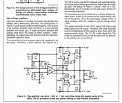
The gain can be determined by solving the circuit equations. Neglect the effects of L1 and R13, and assume an ideal op amp.
The equations are:
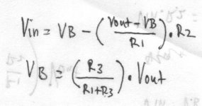
(Vin-Vplus)/R1 = (Vplus-Vout)/R2
Vplus=Vout*Rp/(Rp+R3)
Where Vplus is the voltage at the op amp input terminals. (For an ideal op amp the voltages are the same at both input terminals.) Rp is the parallel combination of R4 and R5.
Solving the above equations gives:
Vout/Vin=R2*(Rp+R3)/(Rp*R2-R1*R3)
The gain for this circuit is 32.
The equations are:
(Vin-Vplus)/R1 = (Vplus-Vout)/R2
Vplus=Vout*Rp/(Rp+R3)
Where Vplus is the voltage at the op amp input terminals. (For an ideal op amp the voltages are the same at both input terminals.) Rp is the parallel combination of R4 and R5.
Solving the above equations gives:
Vout/Vin=R2*(Rp+R3)/(Rp*R2-R1*R3)
The gain for this circuit is 32.
how about the usual way? - do the voltage divider algebra with the ideal op amp assumption that the opamp +,- inputs are held exactly equal by the loop gain
Hi, Sawreyrw,
Thanks for the equation 😀
One dumb question, the gain has (-) sign infront of it, is this circuit is an inverting amplifier?
Thanks for the equation 😀
One dumb question, the gain has (-) sign infront of it, is this circuit is an inverting amplifier?
- Status
- Not open for further replies.
- Home
- Amplifiers
- Solid State
- How to calculate gain?