I got my class D amp working today. It seems to be stable and nothing gets hot without any heatsink with a sinve wave input and 28V bridge suppy into 4ohm after about 45 minutes. However, there is significant 125kHz switching left in my output after the filter. I read a post which I unfortunately can't find where Charles mentioned that some switching is looked at as beneficial in subwoofer applications. That is what my amp will be used for. Is the ~5Vpp too much ripple? I haven't listened to any music yet so I don't know if I can hear the ripple, but is the current amount of ripple too much? I left the filter fc at a relatively high 55kHz [18uH and .47uF] for passing LF signals - should I lower the filter's cutoff? Thank you!
Attachments
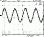
5Vp2p sounds like a lot.
If you really are using IRF6665 with a very low internal capacities, you can increese the switching frequency to about 400-500kHz without incressing the loss in the MOSFET's significantly. This will move the carrier to a higher frequency, where your post filter can supress better.
A higher switching frequency will most likely increese THD, but also give you a higer bandwidth allowing more feedback to eliminate THD. EMI should also be considered.
Of course this is one way of doing it, you could also change your post filter, but it will influence the frequency responce in the high audio range and make it load dependent (8, 4 or 2 ohm speaker).
I personally use a 20uH inductor together with a 1uF capasitor with a 400kHz carrier. I have a huge amount of feedback (PID control) after the post filter, so I have no problem with the frequency response in the high audio range.
With a 60V rail I get about 150mV of carrier ripple at the output. This is probably rather extreme, but I do it because I can.
I can see that you are using a full bridge design. This allows you to supress the carrier, by making it commen mode.
Insted making one side of the H-bridge an inverted version of the other, you could make a tri state design. This is how you do it:
Good luck with it.
If you really are using IRF6665 with a very low internal capacities, you can increese the switching frequency to about 400-500kHz without incressing the loss in the MOSFET's significantly. This will move the carrier to a higher frequency, where your post filter can supress better.
A higher switching frequency will most likely increese THD, but also give you a higer bandwidth allowing more feedback to eliminate THD. EMI should also be considered.
Of course this is one way of doing it, you could also change your post filter, but it will influence the frequency responce in the high audio range and make it load dependent (8, 4 or 2 ohm speaker).
I personally use a 20uH inductor together with a 1uF capasitor with a 400kHz carrier. I have a huge amount of feedback (PID control) after the post filter, so I have no problem with the frequency response in the high audio range.
With a 60V rail I get about 150mV of carrier ripple at the output. This is probably rather extreme, but I do it because I can.
I can see that you are using a full bridge design. This allows you to supress the carrier, by making it commen mode.
Insted making one side of the H-bridge an inverted version of the other, you could make a tri state design. This is how you do it:
An externally hosted image should be here but it was not working when we last tested it.
Good luck with it.
sovadk,
Thank you for the help. Yes, I am actually using the IRF6665. I am fixed at 125kHz and it would take modifying traces under a QSOP part to change the freq.
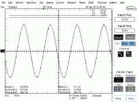
Because I am only interested in using this amp for subwoofer duty I lowered the filter's corner. I also added a 1uF cap across the load which should lower the cutoff more. It's right around 1Vpp ripple at 2/3 power [32.5W@4ohm]. Max power at clipping is 74W@4ohm, shown on the scope capture below. I still have not added feedback.
Thank you for the common mode carrier suggestion 🙂 Perhaps I can implement it in a future design.
Finally, I am concerned about my bridge snubbing. I have a 6ohm in series with a 470pF from the switched output to ground, but no snubbing from the switched output to Vcc. Should I snub both ways? If so, what about a resistor from the switched output and then a cap from the resistor to Vcc and ground vs. a series R and cap from both the switched output to Vcc and ground?
Thank you for the help. Yes, I am actually using the IRF6665. I am fixed at 125kHz and it would take modifying traces under a QSOP part to change the freq.
Because I am only interested in using this amp for subwoofer duty I lowered the filter's corner. I also added a 1uF cap across the load which should lower the cutoff more. It's right around 1Vpp ripple at 2/3 power [32.5W@4ohm]. Max power at clipping is 74W@4ohm, shown on the scope capture below. I still have not added feedback.
Thank you for the common mode carrier suggestion 🙂 Perhaps I can implement it in a future design.
Finally, I am concerned about my bridge snubbing. I have a 6ohm in series with a 470pF from the switched output to ground, but no snubbing from the switched output to Vcc. Should I snub both ways? If so, what about a resistor from the switched output and then a cap from the resistor to Vcc and ground vs. a series R and cap from both the switched output to Vcc and ground?
Attachments
Connecting the zobel network to the ground should be enough. However you should increese the capasitor a lot. You need the zobel network to damp the resonance of the postfilter, in order to avoid large transients (maby several hundreds of volts), when you turn the amplifier off or if the amp puts out frequencys arround the resonance of the post filter. I know that B&O ICEpower use a 5 ohm 25W resistor for their zobel network. They are using another modulatin scheme than you, that generates some frequencys arround the resonance of the post filter. Therefore they need a resistor that can handle higher effects that you probably need. If the speaker you're are targeting, has a low enough resistive load arround the post filter resonance, then you only need the zobel network to handle EMI consideratins. Still you're zobel network is targeting frequencys above 50Mhz, where EMI is a concern down to 1Mhz I think.
Since you're going to use this amplifier in the very low frequency range, you could easily increese the post filter capasitor even more.
Since you're going to use this amplifier in the very low frequency range, you could easily increese the post filter capasitor even more.
Right you are 🙂 Today I played with the cap across the load up to 10uF and saw a reducing in switching past that capacitance value. I was getting down to about 500mVpp ripple which I was happy with so I quit there.
The series R and C I was talking about is from the switched output, between the FETs, not on the other side of the output L where the speaker connects. Sorry if my nomenclature was confusing. What I should have asked was if you snub each FET by itself, or just the lower 2 or upper 2?
Thank you for the help sovadk. I will work on it more tomorrow.
I don't know much about the effect of snubbing the output of the MOSFET's. I know that some reduce the slew rate of the switching waveform to improve EMI ratings, but I presume that It'll give a lot of deadtime=THD.
- Status
- Not open for further replies.
- Home
- Amplifiers
- Class D
- how much residual switching post-filter?