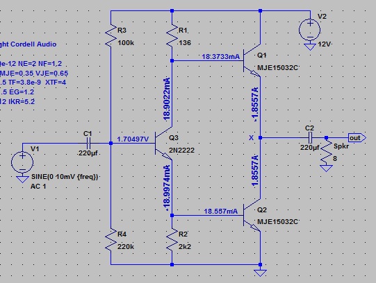
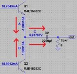
i'm using the following circuit to explore pseudo-pushpull topology, only trying to understand how it works, don't mean to use it for any practical applications at all.
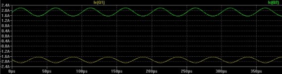
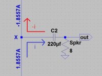
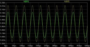
now i have a question. the ac output currents of Q1 and Q2, Ie(Q1) and Ic(Q2), are the same but in opposite directions, going at the same time, as shown below.

so in the output net to speaker, there'd be two currents, same but opposite, going at the same time.
two currents, same and opposite, going in a wire at the same time, what does this mean? could it happen? what did i do wrong in the circuit?
now i have a question. the ac output currents of Q1 and Q2, Ie(Q1) and Ic(Q2), are the same but in opposite directions, going at the same time, as shown below.
so in the output net to speaker, there'd be two currents, same but opposite, going at the same time.
two currents, same and opposite, going in a wire at the same time, what does this mean? could it happen? what did i do wrong in the circuit?
Attachments
Last edited:
The upper output transistor is usually driven from a emitter follower and the lower output transistor is driven from an inverting transistor.
You actually did nothing wrong (though I would have expected the values of R1 and R2 to be the other way round) - you should merely think about your sign definitions again. If current is supposed to go out into the load from both transistors, the Ic(Q1) contribution must have the opposite sign of Ic(Q2). That's Class A push-pull.
Maybe it was a bit unfortunate to plot Ie(Q1) rather than Ic(Q1) (you will find that Ic and Ie are defined such that Ic ~= - Ie).
Homework: Think about sensible values for C1, C2 given a desired 20 Hz - 20 kHz frequency range.
Maybe it was a bit unfortunate to plot Ie(Q1) rather than Ic(Q1) (you will find that Ic and Ie are defined such that Ic ~= - Ie).
Homework: Think about sensible values for C1, C2 given a desired 20 Hz - 20 kHz frequency range.
Last edited:
looks like the "JLH" output stage
I simmed a few variations a while ago http://www.diyaudio.com/forums/solid-state/40355-grahams-class-jlh-output-4.html#post473194
I simmed a few variations a while ago http://www.diyaudio.com/forums/solid-state/40355-grahams-class-jlh-output-4.html#post473194
You actually did nothing wrong (though I would have expected the values of R1 and R2 to be the other way round) - you should merely think about your sign definitions again. If current is supposed to go out into the load from both transistors, the Ic(Q1) contribution must have the opposite sign of Ic(Q2). That's Class A push-pull.
Maybe it was a bit unfortunate to plot Ie(Q1) rather than Ic(Q1) (you will find that Ic and Ie are defined such that Ic ~= - Ie).
Homework: Think about sensible values for C1, C2 given a desired 20 Hz - 20 kHz frequency range.
thank you sgrossklass for your help!
i tried to flip R1 and R2, but i couldn't get the output net voltage to be at the middle of power supply then. this is a minor issue for me now, i'd like to focus on how this pseudo-pushpull output stage works first.
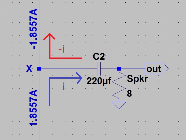
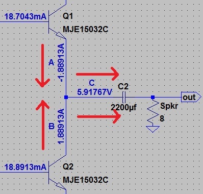
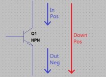
"Ic(Q1) must have the opposite sign of Ic(Q2). That's Class A push-pull. " both currents in terms of Ic, ok cool. that in turn would mean currents in circuit segments A and B be going in opposite directions, as shown in the picture below. that'd leave only one scenario for what would happen in segment C, the two currents would combine and go in the same direction to the speaker. or one current would come out of segment C and split into A and B, then each would go in their own separate ways from there on.
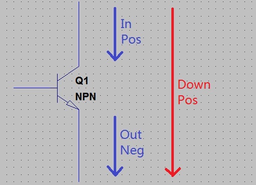
so i now suspect this is the way pseudo-pushpull works, let's call it the working state of such topology. now the confusing thing seems to be LTspice. LTspice seems to always call Ie negative and Ic positive, static, fixed, and always so.
as per the picture below, there is only one current direction with respect to a circuit, blue arrows and red included. but by LTspice definition, there'd be two directions, i.e., there'd be positive and negative directions for the blue arrows. obviously LTspice label dc current this way, as well as plot ac current plots this way, as illustrated in the current plot in my first post. this is what confused me. i was taking the ac current plot as what is actually happening in the circuit, as opposed to current direction with respect to their own bjt's only. LTspice does not reflect what actually happens in a circuit, at least with current? is it really done so? why is it done this way in LTspice?
i also plotted out Ic(Q1) and Ic(Q2), and LTspice shows they go in the same direction, not the opposite, as the class A pushpull definition has it, and the circuit is working.
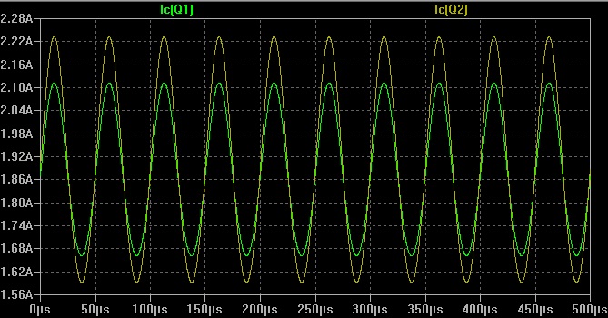
just another evidence supporting the guess that LTspice does it only per its own definition, which may or may not match what is actually happening in a circuit.
now if the "working state" is really the way class A pushpull works, what is so particlular about it then, why is it called pseudo? is it because this topology cannot have a class AB pushpull working state as a real pushpull stage would have?
as for the homework sgrossklass, that's tough. i'm not there yet, just quickly gave it a try in LTspice, without any theory behind it. C1 seems to have an obvious effect on the lower frequency end, and C2 the higher, (why is it so)? but C2 seems to be much less effective then C1. C2 only made a very gradual sloping down, not a nice and sharp rolloff. plus, C1 and C2 had impact on each other, one changes and the other changes with it. so could i make this the second priority for now?
if i got the above right, i'll then have a follow up question. 🙂
Attachments
Last edited:
The upper output transistor is usually driven from a emitter follower and the lower output transistor is driven from an inverting transistor.
thank you nigelwright7557!
too bad i'm not there yet to explore what happens with emitter follower and/or active load, and other techiques, and the advantages/disadvantages of doing that. hopefully i'll get there not too late. 🙂
looks like the "JLH" output stage
I simmed a few variations a while ago http://www.diyaudio.com/forums/solid-state/40355-grahams-class-jlh-output-4.html#post473194
thank you jcx!
thank you for pointing me to the thread, very interesting. it's also a long thread heavily loaded with "stuff" as well. marked it and will go read it more slowly and carefully again, and probably again, and again.
as you can see, i'm not on that advance level yet, i'm trying though 🙂
yes, the JLH is where i saw the so called pseudo-pushpull first, and i'd like to understand how it works now.
Last edited:
Simply, the emitter current is leaving the node (emitter is sourcing the current). And all "sourcing" currents are negative in LTspice (plot Q1 collector current). In fact all simulation programs use this convention and also in datasheet for a digital circuit.
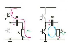
As for the circuit, in ordinary class B push-pull amplifier only one transistor conducts for a given signal cycle.

For positive half cycle the upper transistor deliver current the the load by charging capacitor. And for negative half cycle lower transistor discharge capacitor.
As you can see upper transistor pushing current through the load for positive half. And lower transistor pulls the current from the load.
But for your "pseudo" push-pull amplifier both output transistors conduct over the entire signal cycle. And in this case I_load = I_upper - I_lower.
http://sound.au.com/tcaas/jlhoutput.pdf
As for the circuit, in ordinary class B push-pull amplifier only one transistor conducts for a given signal cycle.
For positive half cycle the upper transistor deliver current the the load by charging capacitor. And for negative half cycle lower transistor discharge capacitor.
As you can see upper transistor pushing current through the load for positive half. And lower transistor pulls the current from the load.
But for your "pseudo" push-pull amplifier both output transistors conduct over the entire signal cycle. And in this case I_load = I_upper - I_lower.
http://sound.au.com/tcaas/jlhoutput.pdf
Attachments
Last edited:
Q3 feeds inverted phases to output transistors of the same polarity. In a theoretical circuit as yours in post #1, both output transistors should be fed from Q1 emitter or, if you want to reverse the phase, from the collector.
i'm using the following circuit to explore pseudo-pushpull topology, only trying to understand how it works, don't mean to use it for any practical applications at all.
It's identical to the output stage of a TTL logic gate, and also to that of a vacuum tube, OTL output stage where you have no choice since there's no such thing as a "P-Channel" VT.
now i have a question. the ac output currents of Q1 and Q2, Ie(Q1) and Ic(Q2), are the same but in opposite directions, going at the same time, as shown below.
so in the output net to speaker, there'd be two currents, same but opposite, going at the same time.
two currents, same and opposite, going in a wire at the same time, what does this mean? could it happen? what did i do wrong in the circuit?
Two currents in opposite directions means that the load current is the differential current. This applies for every PP output regardless of whether it's vacuum tubes driving a center tapped primary, a totem pole OTL (hollow state or solid state) or an OTL Circlotron. No differential current, no output. (And no DC core magnetization for a PP OPT when the finals are drawing equal Q-Point currents.)
In this case, the output from the Q3 "cathodyne" is two signals: anti-phase to the input at the collector, and in phase at the emitter. When the base of Q2 is going positive (i.e. turning on) the base of Q1 is turning off as it goes more negative. If neither phase cuts off, you have Class A operation. If one side does cut off, then it's Class AB, B or C.
push pull class A.
This is quite interesting configuration of output stage. Actually, referencing to "Audio Power Amplifier Design Handbook", it combines VAS and Output stage into one! What's more, you can put miller cap crossing output stage. As there are only 2 transistors inside loop, the inclusive miller compensation will be stable anyway.
This is quite interesting configuration of output stage. Actually, referencing to "Audio Power Amplifier Design Handbook", it combines VAS and Output stage into one! What's more, you can put miller cap crossing output stage. As there are only 2 transistors inside loop, the inclusive miller compensation will be stable anyway.
push pull class A.
This is quite interesting configuration of output stage. Actually, referencing to "Audio Power Amplifier Design Handbook", it combines VAS and Output stage into one! What's more, you can put miller cap crossing output stage. As there are only 2 transistors inside loop, the inclusive miller compensation will be stable anyway.
thank you jxdking and everyone else for your inputs!
i actually did put caps on the output transistors, LTspice said the THD would be lower as well, so why not. would that slow down the amp?
also, although everybody says push pull class A, but it's actually a misnomer, it that right? how can class A have push pull action, or how can push pull be class A?
if i guessed right, then the way the so called pseudo-pushpull class A work is the two output currents combining into one, going in the same direction into the speaker, or the reverse. could this be a correct guess?
Most folk would call this style of output stage a quasi complementary push pull.
There is a wonderful old Thread started by our Member Quasi that discusses the design and build and completed projects, virtually all based on the quasi complementary ClassAB types. He did a complementary design as well.
Well worth reading and possibly copying one of his low power designs and comparing to a JLH. JLH also did complementary ClassAB.
also, although everybody says push pull class A, but it's actually a misnomer, it that right? how can class A have push pull action, or how can push pull be class A?
Class A means a duty cycle of 360deg. This can apply to SE designs as well as to PP designs. If push-pull, the duty cycle becomes +/-360deg. For audio, all SE stages have to be Class A as that's the only way to reproduce the entire signal cycle. PP can also be Class A if neither device cuts off at any point in the signal cycle.
if i guessed right, then the way the so called pseudo-pushpull class A work is the two output currents combining into one, going in the same direction into the speaker, or the reverse. could this be a correct guess?
The load always sees the differential current.
Yep.PP can also be Class A if neither device cuts off at any point in the signal cycle.
A little example with numbers:
Let's say that quiescent current be 1 A.
Now let upper transistor Ic increase to 1.1 A, and lower transistor Ic decrease to 0.9 A.
Since the upper transistor sources more current than the lower one sinks, the difference of 0.2 A goes out into the load. Each transistor is deviating from quiescent state by 0.1 A.
As you can plainly see, both transistors are conducting at this point, so it's obviously Class A. In addition, each transistor contributes half the load current, i.e. they're working in tandem - push-pull operation.
Things would remain in Class A up to the point where lower transistor current approaches zero (1 A down from quiescent). Then upper transistor current is up to almost 2 A (1 A up from quiescent). So you get 1 A + 1 A = 2 A going out into the load.
You can also look at it another way - if the upper transistor runs at 2 A but the lower one at close to zero current, the difference has to travel to the load (since where else should the current go if the lower transistor does no longer really feel like conducting?).
So with a 1 A quiescent current, you get a peak output current of (almost) 2 A in Class A.
That's a factor of 2 more than a SE circuit, which can never sink more than Iq and as such would be limited to 1 A.
Last edited:
It would be wrong though: this topology already existed in the tubes days, when complementarity didn't exist, even in the wildest designers fantasies.Most folk would call this style of output stage a quasi complementary push pull.
"Quasi" refers to the practice of replacing one of the OP transistor (generally the P one in the silicon era, and the N in the good ol' Ge times) by a composite having the driver of the desired polarity.
Bengt Olson (IIRC) has coined another term for topologies synthesizing the opposite polarity from purely single-sex transistors: virtual complements.
Self doesn't like it, but I think it is a good descriptor of what this topology does.
Hi Guys
Read post-9 until you understand the fact that at power-up the output cap is charged up and retains the voltage across itself in "battery-like" fashion. Thinking of the voltage across the cap this way makes understanding the circuit operation easier.
Post-10 is incorrect.
Also, there is no such thing as "pseudo-pushpull"; the circuit is either push-pull or single-ended the way the terms are defined. As others have pointed out, the three- transistor circuit is just John Linsley-Hood's driver and output stage from his 1969 class-A amp. Add a PNP input with feedback from the output node and you have the whole circuit. His was intended to be as economical as possible and to sound as tube-like as possible.
Have fun
The term usually used is quasi complimentary.Hi Guys
Also, there is no such thing as "pseudo-pushpull"; the circuit is either push-pull or single-ended the way the terms are defined.
Have fun
Hi Guys
The circuit posted is not quasi-comp. Besides, whether a circuit is a totem-pole, quasi, fully-complimentary has no relevance to the "pseudo-push-pull" misnomer.
Time to open some books...
Have fun
The circuit posted is not quasi-comp. Besides, whether a circuit is a totem-pole, quasi, fully-complimentary has no relevance to the "pseudo-push-pull" misnomer.
Time to open some books...
Have fun
- Status
- Not open for further replies.
- Home
- Amplifiers
- Solid State
- how does pseudo-pushpull work?