I take an inductance reading with no DC current, then I send current through the choke until the inductance drops by about 15%, then that's my estimate for inductance and current.
It's a total pain to do this!
It's a total pain to do this!
Would an LCR meter actually give a useable result.
Often DC chokes change their inductance depending on the DC current through them.
Often DC chokes change their inductance depending on the DC current through them.
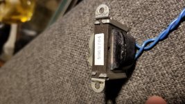
Start with the DCR and looking at the winding wire size (perhaps visible through the semi-clear former).
The DCR and the size of the choke can provide an estimate of the maximum internal power loss with a certain level of DC current, when comparing with similar sized chokes with similar DCR.
The link provides a relatively straightforward way to measure inductance with DC current:
https://www.dalmura.com.au/static/Choke%20measurement.pdf
Would an LCR meter actually give a useable result.
Often DC chokes change their inductance depending on the DC current through them.
You can use an LCR meter but decouple it from the choke with some big 10,000uF bipolar capacitors. Next setup a DC bench supply with an adjustable current source feeding the choke.
In this manner, you can watch the inductance drop as DC current is applied. The adjustable current source isolates the LCR meter from the bench supply and the caps isolate the LCR meter from the DC voltage.
An LCR meter needs to test at a lowish frequency, well enough below the choke self resonance, and the CC needs to block any LCR meter test current sufficiently to not offset the choke measurement current.
Painful choke measurements
Yep, it can be a pain.
djn, if you think that the chokes were intended as filters for power supplies, and that's how YOU want to use them, then Sherman Hubelhank's test regime is as relevant now as it was when he published it in 1956. IF YOU THINK THE CHOKES WERE DESIGNED FOR ANOTHER PURPOSE, THIS METHOD IS NOT SO USEFUL AND COULD HARM YOUR CHOKES. With that in mind:
When you plot the results of inductance L in Henrys versus current in mA, you get a curve that rises from low values of L at low current, plateaus across a usable range of currents, and then rolls off as current increases.
In practice, choke constructors and designers take as key parameters the frequency being rectified and the likely current to be drawn. They use those data to estimate core size, wire gauge, number of turns and any air gap necessary to deliver the required inductance at the required current without saturating the core.
Sherman worked for the Connecticut Telephone and Electric Corporation. Joe Roberts re-printed Sherman's method in the Fall 1994 edition of Sound Practices. I recall Joe recently replying to a post on this site offering CDs of the Sound Practices collection - I highly recommend it.
I take an inductance reading with no DC current, then I send current through the choke until the inductance drops by about 15%, then that's my estimate for inductance and current.
It's a total pain to do this!
Yep, it can be a pain.
djn, if you think that the chokes were intended as filters for power supplies, and that's how YOU want to use them, then Sherman Hubelhank's test regime is as relevant now as it was when he published it in 1956. IF YOU THINK THE CHOKES WERE DESIGNED FOR ANOTHER PURPOSE, THIS METHOD IS NOT SO USEFUL AND COULD HARM YOUR CHOKES. With that in mind:
- Apply mains power to a transformer primary and full-wave rectify the secondary
- Across the rectified output, attach in series an ammeter, the choke, and a hefty rheostat (1kOhm to 2kOhm, good for a Watt or more)
- Start with the rheostat at maximum resistance and adjust it to achieve a plausible current (say, 50mA for a small filter choke)
- With a DMM, measure the RMS voltage across the choke (Vc), the voltage across the rheostat (Vr) and (with the power off!!) the resistance of the rheostat (R)
- Estimate L = (Vc * R)/(Vr * 4 * Pi * f) where f is your mains frequency (usually 60Hz in USA, 50Hz where I live)
- Record the result, repeat the procedure at other plausible currents covering your likely range of operation
When you plot the results of inductance L in Henrys versus current in mA, you get a curve that rises from low values of L at low current, plateaus across a usable range of currents, and then rolls off as current increases.
In practice, choke constructors and designers take as key parameters the frequency being rectified and the likely current to be drawn. They use those data to estimate core size, wire gauge, number of turns and any air gap necessary to deliver the required inductance at the required current without saturating the core.
Sherman worked for the Connecticut Telephone and Electric Corporation. Joe Roberts re-printed Sherman's method in the Fall 1994 edition of Sound Practices. I recall Joe recently replying to a post on this site offering CDs of the Sound Practices collection - I highly recommend it.
Woops! redundant post
WOOPS! Didn't see trobbins link and lovely write-up! My apologies for repeating advice 😱🙄
The link provides a relatively straightforward way to measure inductance with DC current:
https://www.dalmura.com.au/static/Choke%20measurement.pdf
WOOPS! Didn't see trobbins link and lovely write-up! My apologies for repeating advice 😱🙄
Yeh Sherman Hubelhank's article (link to article in my doc) is the earliest similar technique to what i have been using for a few years.
As I have the jig setup bits prepared, and can use MS Excel to input measurements, and seem to have to do this kind of test a few times a year, I find it relatively easy to do a few quick test points and the deduce what the choke can be used for.
It does take longer to do a L versus Idc for a constant Vac across the choke, or some other specific characteristic curve, if there is a need to do that, but in general taking about 2-4 measurement points is often sufficient to 'pigeon hole' an unknown choke.
Why not use the headphone out on your computer to play a YouTube sine wave through the choke and small series resistor. Measure the voltage across the resistor to get current and use that with voltage across the choke to work out : L=V(6.28 x the AC frequency x current ) There's a more complicated way to factor in the DCR loss across the inductor but I think (and correct me if I'm wrong) the simple one would get you close enough for an idea.
Or if you have a signal generator (or having measured the DCR of the choke to make sure the applied voltage won't kill it, a source of AC like from a low voltage filament transformer), you can measure the voltage across the choke and the current and then do the calculation.
Also methods 1 and 2 on this page are easy with calculator included:
How To Measure Inductance - Daycounter
Yes that is the basic way to measure inductance, but it doesn't go to the DC current carrying capability performance of the choke for DC power supply filtering applications.
With no idea what tools djn has my thought it was an easy way to get started without more than a DMM. The inductance and DCR relative to core size might help make a starting guess about current capability, though nothing of voltage safety.
The DCR and the size of the choke can provide an estimate....
Agree strongly. DCR, pounds, and the Hammond listings tell you enough to use the choke for DC power filtering where precision is thumb-wide. 5H, 8H, 100mA, 150mA, all the same to us.
Agree - that is an experienced assessment of the former and insulation covering, and creepage and clearance distances to core, and preferably an insulation resistance test to at least 1kVdc if the aim is to use it for typical B+ filtering.... though nothing of voltage safety.
If the winding is a single cluster on a former, rather than using layers and inter-layer insulation, then there is some risk of using the choke for a choke input application where the applied turn-to-turn voltage may be high.
Last edited:
If unsure about voltage safety, you could also put the choke on the negative (ground) side of the voltage supply, whereby there will be a lot less voltage potential between its windings and its core (and the chassis). It will do its job just as well.
Ground side choke location lets through some parasitic hum coupling via the winding to core capacitance. Whether that is relevant to the intended 'job', only djn may know.
Just bias up the frame to B+ and mount the choke on an isolated piece of acetal. Problem solved!
Just bias up the frame to B+ and mount the choke on an isolated piece of acetal. Problem solved!
I hope no one takes this seriously.
- Home
- Amplifiers
- Tubes / Valves
- How do I find the value of this choke?