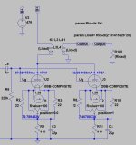
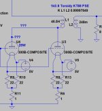
Newby question... I'm redrawing the Andrea Ciuffoli PSE 300B "reference amp" circuit so I'll have an "as built" drawing as I go along. I want to use Coleman regulators instead of the AC heated 300B's in the original schematic. Posted below is the original schematic and my work-in-progress schematic. My question is in red on my schematic, would someone help me complete the 300B circuit to ground so I can draw it? The original design used AC heating and returned the tube to ground via the CT of the filament transformer.
Work in progress schematic:

Original design:


Work in progress schematic:
Original design:
I would send an email to Rod. I wonder if it's possible to parallel the filaments and use a single regulator per channel.
Maybe you have to have a single regulator per channel since having two slightly different voltages on each 300b might create problems.
Maybe you have to have a single regulator per channel since having two slightly different voltages on each 300b might create problems.
If the regulator is set to control current through the filament, then you probably need a separate regulator for each tube. A single current regulator feeding two tubes can't sense any differences in the filaments and if one burns out the other gets twice the current it should have and will probably burn up too.
I looked at Rod Coleman's web page and he mentions the regulator controlling the current through the filament and also having a voltage control function.
I looked at Rod Coleman's web page and he mentions the regulator controlling the current through the filament and also having a voltage control function.
You have to do one virtual cathode for each power tubes.
Thanks!, this is a big help in figuring out the mechanicals of the PSU enclosure(s). The original design had an AC center tap to gnd, basically this is a DC virtual CT to ground, makes sense. I can plan space for dual raw DC supplies. It will be a three enclosure setup, two matching PSU's 8.5 W x 12 D x 5 H (5AR4 fully enclosed), and one amp chassis 17 W x 12 D x ?? H (inches). The Colemans will be in the amp chassis, and the raw DC supply(ies) in the PSU chassis.
Thanks again, completed the cathode circuit. I would think the calibration procedure for an amp like this would be like the 3 steps below, correct? One more question though... There are two test points below each 300B to measure the voltage drop across a 1R resistor. Would the reading at these points be half the full 140mA through both tubes? IOW each TP as I set it up here would be reading the current through just that one tube right, so 70mV? So if you put two DMM's under each 300B you should be trying to compromise each to read close to 70mV as you adjust the bias V, to sum to 140mV?
1) Set bias to -100 volts (or less) to cutoff tubes
2) Set all Coleman regulators so the filaments come to rest at 5V
3) Increase bias while monitoring tube current until total current is 140mA through both tubes

1) Set bias to -100 volts (or less) to cutoff tubes
2) Set all Coleman regulators so the filaments come to rest at 5V
3) Increase bias while monitoring tube current until total current is 140mA through both tubes
I think I see another error. I wanted the volume control to be assignable (or defeatable) on either the RCA or the XLR inputs, assigning removes the volume control from the opposite input. However, it looks like the input transformer secondary will be left "floating" with no load when the volume is switched to the RCA side. I think I need a different switching arrangement so that when the volume control is removed from the Jensen it substitutes in a 50K resistor across the Jensen secondary, so it never leaves an inductive device like the input transformer floating.
Did you hear back from Coleman? I'd be interested in his recommendations. I found him incredibly helpful when I was planning on using 5V as well as 2.5V 300B tubes.
In this iteration assigning the volume control to the RCA input will not leave the IPT floating, the RCA position will shunt a 50K resistor across the secondary where the volume control would be if it were assigned to the XLR. In XLR position the volume control is the shunt and the 50K is disconnected.

Euro21 is of course correct - the problem is the need to adjust the bias for each DHT.
If they are not matched the operation and sound will suffer.
With an IT, only one bias voltage is possible, so the adjustment must be made in the cathode.
BUT the Raw DC can only be shared if the filament regulator's negative sides are both at the same voltage [using my V9 Regulator].
My suggestion - combination bias. Let the grid negative voltage do almost all the bias, and add some filament bias to provide adjustment to match anode current in both tubes. Separate filament regulator, but shared transformer and Raw DC.
2.5V or even lower differential voltage should be enough to match reasonable pairs of 300Bs.
A 2.7 or 3.3Ω main resistor can be trimmed downwards by adding larger value parts until the anode currents converge.
This serving suggestion works with the V9 regulator; it will not work so well with older versions.
Thanks Rod! It's all starting to make sense. I like the ability to nail the anode current balance with hybrid bias. I did come upon a sentence in Andrea's original design article. He suggested using the grid stoppers to trim the balancing act. But trimming one or the other tube in the cathode seems more reliable to me in the end without causing other problems in the grid circuit. Also one wouldn't want an owner to have to install resistors with a tube change, or have to go to a technician. But I think one can use a rotary switch (with healthy contacts) to substitute a small range of resistors. I think a non-technical person can then follow a set of re-calibration instructions, if everything is adjustable. This brings me to the question... What is that calibration procedure? You have adjustment points and test points, the regulators adjust easily, now the filament bias resistors adjust easily, and the main bias adjusts easily. For test points you have each filament voltage that must land at 5V, the anode current of V1, the anode current of V2, the bias voltage. Would the re-calibration procedure have to reset the filament to 5V each time you "try out" a different filament resistor in order to notate the tube current? I would think you would need to adjust the "hotter" tube of the pair downward in current until they match. A user can determine what tube runs hotter with a pre-test of the tubes, then instructed from there the calibration instructions.
If you have almost identical (as sellers apostrophise "pair") output tubes (within one-two milliAmper anode current difference at given bias and anode voltage) and DC filament heating (as R.C.), try "hum balance" potentiometer for equalize small anode current imbalance.
It's only "beauty patch", but decrease a little the distortion (if Gm also almost equal).
Sample:

It's self/cathode biased version, but working in case of DC/fixed bias.
It's only "beauty patch", but decrease a little the distortion (if Gm also almost equal).
Sample:

It's self/cathode biased version, but working in case of DC/fixed bias.
If you have almost identical (as sellers apostrophise "pair") output tubes (within one-two milliAmper anode current difference at given bias and anode voltage) and DC filament heating (as R.C.), try "hum balance" potentiometer for equalize small anode current imbalance.
It's only "beauty patch", but decrease a little the distortion (if Gm also almost equal).
That is an elegant solution for trimming as well! It's not a big deal for someone to purchase "matched" tubes these days, so if this method can vary the bias within the small amount needed to match the tubes that's enough. Directing an owner to only install matched tubes in the first place is probably a good idea and expected.
- Home
- Amplifiers
- Tubes / Valves
- How do I complete this dual Coleman cathode circuit?
