Hi to all.
I am confused in the subject of Class A biasing.
The DC voltage for the output of a push-pull is +20 VDC and -20 VDC. Output is from the emitter (emitter follower). If we consider the + voltage where should the dc bias set? At ~10V or ~20V ? The transistors are in the active region and collector saturation =0V.
Why is it advisable to bias at ~50% of the load line?
I understand this for single ended Class A where the output device has to work for both the positive and negative signal.
But with push-pull why to not take advantage of more than 50% of the available voltage?
Thank you all,
Dimitrios
If you have a negative supply voltage as in +/-20VDC, the 50% point is zero VDC.
Many class-A amplifier designs are less than professional. Don't be surprised if you see something that seems illogical.
Many class-A amplifier designs are less than professional. Don't be surprised if you see something that seems illogical.
Thank you steveu.
What I meant was 50% of +20VDC (=10VDC point), equally -10VDC on the negative line.
Regards
What I meant was 50% of +20VDC (=10VDC point), equally -10VDC on the negative line.
Regards
It might help if we could see a diagram of the kind of stage you mean.
If it is a conventional NPN/PNP follower then I wonder if you are confusing DC voltage operating points and the required DC bias currents relative to the load to be driven.
The two are independent and the output quiescent voltage would normally always be 'zero' to allow maximum swing in either direction.
Mooly thank you.
This is a Class B output which can biased to class AB. How do I get the maximum of class A?😱
An externally hosted image should be here but it was not working when we last tested it.
This is a Class B output which can biased to class AB. How do I get the maximum of class A?😱
That output stage can be biased to run from zero bias (Class B) all the way to full Class A. The bias current needed for Class A depends on the load impedance you want to drive and the maximum output voltage that you want the stage to remain in Class A for.
If you drive the stage beyond its Class A point (whatever that is and that you have set) then the stage simple slides over into Class AB
If you drive the stage beyond its Class A point (whatever that is and that you have set) then the stage simple slides over into Class AB
Have to dash but have a look at these.
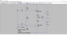
Class B and Class A. The Class A is set to just 22ma bias which means it only remains in class A for low output currents. If we drive the stage harder it moves to Class AB... and so we then need to increase the bias current even more to suit the intended load.
Class B and Class A. The Class A is set to just 22ma bias which means it only remains in class A for low output currents. If we drive the stage harder it moves to Class AB... and so we then need to increase the bias current even more to suit the intended load.
Attachments
You're welcome 🙂
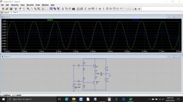
Just so that it all makes a bit more sense......
In the above example we have no DC bias voltage between the base of the output transistors and this in turn means the input signal has to overcome the 0.6 volts B-E turn on voltage before anything happens.
That is a bit unrealistic and is the reason for the apparently low amplitude of the basic Class B example when supplied with only 1 volt peak of signal.
If we make the bias voltage variable (the resistor bias chain is now a voltage source which makes it easier to follow and work with) we can increase this bias voltage right up to the point where the transistors begin to conduct. This still satisfies the Class B definition (zero bias current) but now means the transistors are now ready to conduct more readily and do not need the input signal to first have to exceed the 0.6 volts Vbe.
In other words they are biased right up to the point of begining to conduct.
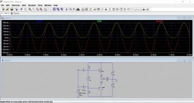
So we get this (first image). Still Class B but much less distortion.
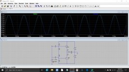
Now we move on to Class A. The input signal has been raised to 10 volts peak and the load current is now also 10 volts peak but crucially we can see that there is now 100ma peak signal flowing in the load.
What bias current do we need to ensure Class A operation? (Second image) Note... the display is now showing load current rather than output voltage.
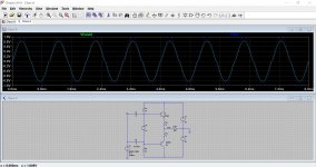
In our example, 100ma peak signal flowing in the load means that we need a static bias current of 50ma flowing in the transistors. When this occurs the current in each transistor when driving the load will vary from 0ma to twice the set bias current (100ma). So neither transistor is cut off at any point (it is in Class A) and it can supply the required load current in this 'always conducting' state. This is seen by looking at the currents in R1 and R2, the 1 ohm resistors.
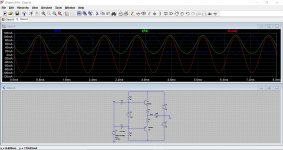
The third image shows the effect of increasing the signal to 15 volts. Now we have 150ma peak current in the load but the transistors are now being forced into their 'cut off' region where each becomes non conducting over part of the cycle. At this point the stage has moved from Class A to what many would call 'overbiased' Class AB operation.
Just so that it all makes a bit more sense......
In the above example we have no DC bias voltage between the base of the output transistors and this in turn means the input signal has to overcome the 0.6 volts B-E turn on voltage before anything happens.
That is a bit unrealistic and is the reason for the apparently low amplitude of the basic Class B example when supplied with only 1 volt peak of signal.
If we make the bias voltage variable (the resistor bias chain is now a voltage source which makes it easier to follow and work with) we can increase this bias voltage right up to the point where the transistors begin to conduct. This still satisfies the Class B definition (zero bias current) but now means the transistors are now ready to conduct more readily and do not need the input signal to first have to exceed the 0.6 volts Vbe.
In other words they are biased right up to the point of begining to conduct.
So we get this (first image). Still Class B but much less distortion.
Now we move on to Class A. The input signal has been raised to 10 volts peak and the load current is now also 10 volts peak but crucially we can see that there is now 100ma peak signal flowing in the load.
What bias current do we need to ensure Class A operation? (Second image) Note... the display is now showing load current rather than output voltage.
In our example, 100ma peak signal flowing in the load means that we need a static bias current of 50ma flowing in the transistors. When this occurs the current in each transistor when driving the load will vary from 0ma to twice the set bias current (100ma). So neither transistor is cut off at any point (it is in Class A) and it can supply the required load current in this 'always conducting' state. This is seen by looking at the currents in R1 and R2, the 1 ohm resistors.
The third image shows the effect of increasing the signal to 15 volts. Now we have 150ma peak current in the load but the transistors are now being forced into their 'cut off' region where each becomes non conducting over part of the cycle. At this point the stage has moved from Class A to what many would call 'overbiased' Class AB operation.
Attachments
Pure Class A bias is simply based on U = Rload x I
You should end up with constant power supply draw wathever the music played.
Yes, same power when idling or playing.
A very non efficient way, but perfect great quality for low power, and in a lot of cases that is good enough.
Heat, large heat sinks but a mostly easy design to readily get excellent quality and happy neighbours.
From thermal runaway view, it is better to replace the base-emitter resistor by diodes of the same Vτ than the transistors, and to add a small emitter resistor. The coupling between diodes and transistor would be so hard as you can, and still better, use a VBE multiplier. Diodes, also, has little internal signal resistance, so only one capacitor is needed, in the medium of them, and not two on each base. Also, a DC feedback is necessary in order to maintain DC at zero in the emitters and prevent speaker coil damage or displacement.
Mooly,
so for an anticipated max 4 amps load current the transistors should be biased to continuously conduct 2 amps each?
This can be achieved via the voltage bias chain?
Correct?
so for an anticipated max 4 amps load current the transistors should be biased to continuously conduct 2 amps each?
This can be achieved via the voltage bias chain?
Correct?
Four amps delivery would be to much for such a simple single transistor pair to work with. Yes, you could bias them to this value but the base current needed would be so large that the overall input impedance would be very low and unpredicatable and the overall performance totally unacceptable. You would need a small power amp to drive the signal into them 🙂
So you would need a different approach such as incorporating driver transistors and then wrapping feedback around them in the form of a more conventional set up.
It all depends on what you want really. A stage like this runs totally open loop with no overall feedback and that makes the performance very poor... even though its still Class A.
I tried it for interest. At 2 amp bias current and 4 amps signal into a 4 ohm load the source driving it needs to deliver around 130ma peak drive current. Also look how low the input impedance is going to be with those 500 ohm resistors (so 250 effectively) plus whatever the transistors pull it down by.
Hope it makes sense. Voltage scales on the left, current on the right. The small red trace is the current drawn from the signal source driving the stage.
Attachments

From thermal runaway view, it is better to replace the base-emitter resistor by diodes of the same Vτ than the transistors, and to add a small emitter resistor. The coupling between diodes and transistor would be so hard as you can, and still better, use a VBE multiplier.
One of the lesser-known advantages of Class-A is that you don't have to bother with matching diodes and stuff because you can control the quiescent currently as closely as you like by feedback control. This cannot be done for Class-B.
Your diagram is lacking the vital resistors in series with the transistor emitters; as shown the quiescent is virtually uncontrolled and there will be smoke.
You will see that Mooly has added 0.1R resistors on his simulation schematics.
In push-pull Class-A the SUM of voltages across these two emitter resistors is constant despite the current flowing in and out of the load. You can use this voltage to control the quiescent current by negative feedback, with great accuracy.
This idea was originally published in Electronics World in 1996, and is described in detail in my power amplifier book.
Last edited:
One of the lesser-known advantages of Class-A is that you don't have to bother with matching diodes and stuff because you can control the quiescent currently as closely as you like by feedback control. This cannot be done for Class-B.
Your diagram is lacking the vital resistors in series with the transistor emitters; as shown the quiescent is virtually uncontrolled and there will be smoke.
You will see that Mooly has added 0.1R resistors on his simulation schematics.
In push-pull Class-A the SUM of voltages across these two emitter resistors is constant despite the current flowing in and out of the load. You can use this voltage to control the quiescent current by negative feedback, with great accuracy.
This idea was originally published in Electronics World in 1996, and is described in detail in my power amplifier book.
Thanks guy. I'm not too common with class A transistors as Class A MOSFET or Tubes. The only one time I had at hand it was an old transistor radio for Fiat 600 with a Germanium device loaded with an autotransformer, more than 3 decades ago.
Apologize for my possible mistakes.
DouglasSelf
Thank you for commenting.
Yes, the Re resistors are missing in the original (generic) circuit.
Thank you also for your excellent reference books.
The question of how (or how much) to bias a push-pull Class A came up from a sentence in your your book (5th edition).
From the "Class-A Power Amplifiers" chapter page 301 paragraph 5, I quote:
"...this one will operate effectively in pure push-pull Class-A if the quiescent bias voltage is sufficiently increased; the increment over Class-B is typically 700mV depending on the value of the emitter resistors." My underline.
This requires some analysis for newbies like me.
Thank you,
Dimitrios
- Status
- Not open for further replies.
- Home
- Amplifiers
- Solid State
- How do I bias a push-pull class A amplifier?