A question about optimum horn termination:
What is the most optimum shape to terminate a horn?
-The 180 degree-version has a complete rondover but the radius is smaller given a constant horn witdth.
-The 135 degree-version has compromized the end of the roundover for a larger radius and a slightly longer/larger horn.
The intention is to use it in a MEH/synergy-configuration. Hence, the horn will be used below its cut off frequency.
Any other suggestions?

Thanks
Petter
What is the most optimum shape to terminate a horn?
-The 180 degree-version has a complete rondover but the radius is smaller given a constant horn witdth.
-The 135 degree-version has compromized the end of the roundover for a larger radius and a slightly longer/larger horn.
The intention is to use it in a MEH/synergy-configuration. Hence, the horn will be used below its cut off frequency.
Any other suggestions?
Thanks
Petter
Hello. I am far from an expert. However, you may wish to look at threads here (some very, very lengthy 😀 ) that discuss the horn or waveguide. I use a ready made speaker (Yorkville Unity U15) that I can tweak. As I understand it, the main benefits of a rounded mouth are reduced diffraction. Much of this can be achieved even with a budget waveguide using the towel (or foam, or ...?) around the mouth, Geddes foam plug, etc. Of course, note that what the towel tweak gains in being cheap, it loses in being visually unappealing.
Factors Affecting Sonic Quality of Mid & HF Horns & Waveguides
Factors Affecting Sonic Quality of Mid & HF Horns & Waveguides
Last edited:
A question about optimum horn termination:
What is the most optimum shape to terminate a horn?...
An excellent question, for which there does not appear to be a definitive answer, unfortunately.
However, numerical simulation software and hardware is now with reach of DIY, so you could learn ABEC or Axidriver and try some experiments.
Probably the next step up for DIY audio enthusiasts, so I have started to learn ABEC myself to answer just such questions.
Over the small variation of your example I suspect it would make very little difference.
I also suspect a curve that slowly decreases in radius should be better, but similarly a very small difference.
Best wishes
David
Last edited:
Shape: non-circular curve of increasing curvature. Avoid discontinuity in 2nd. derivitive.
Angle: Free Standing, 180 deg.
Flat baffle, 90 deg.
WHG
Angle: Free Standing, 180 deg.
Flat baffle, 90 deg.
WHG
Thanks all for your input. I'll be doing some thinking and planing. May have to learn ABEC to minimize the number of test boxes...
There is a lot to read here (should be the same 128 page-document):
JMMLC Lecture on Horns | Phonograph | Finite Element Method
https://vdocuments.mx/jmmlc-lecture-on-horns.html
What caught interest was the Min phase horn (page 125) by Michael Gertgrasser. It says "Gauss optimized". However, no equation or futher references were found. Compare the simulations to the one for OS on page 122 and 126 with different roundovers.
Reverse engineering regarding Gaussian distribution gives that a Probability Density Function for a Normal distribution plot that follows a Gaussian distribution. Very convenient.
See here:
Normal distribution - Wikipedia
Set µ = 0 and sigma to whatever you like. I picked 4.
By doing this, you will get a S-shaped curve where small X is similar to an OS profile and large X results in that Y flattens out horizontally. I then mirrored the coordinates after the maximum angle was reached in the maximum angle direction which forced the Y increase instead of flattening out. This way, the shape looks like an OS-shape with a large roundover. There are some differences though.
- The initial expansion is slower for the Gaussian compared to OS. (Fig.1)
- The length of constant angle expansion in shorter in the Gaussian (Fig 2) expansion.
- The mouth roundover is both smoother and greater in the Gaussian expansion. (Fig 1 & 2)
- The derivate does not show discontinuities in the Gaussian expansion. (Fig 2).
- When moving the Gaussian expansion slightly to the left, they both look very similar to the eye until the roundover starts. (Fig 3).
Both curves has 0 degree starting angle. The roundover for the OS was set to 1/4 wavelength of the cut of frequency given by equation #24 by Kolbrek for a 1" throat and theta = 45 degree (90 degree coverage angle):
https://www.audioxpress.com/assets/upload/files/kolbrek2885.pdf
Fig 1
Fig 2, derived. Note the discontinuity and the difference in constant coverage angle length.
Fig 3, equal to Fig 1, only with the Gaussian expansion moved to the left.
Anyone else thought about this?
JMMLC Lecture on Horns | Phonograph | Finite Element Method
https://vdocuments.mx/jmmlc-lecture-on-horns.html
What caught interest was the Min phase horn (page 125) by Michael Gertgrasser. It says "Gauss optimized". However, no equation or futher references were found. Compare the simulations to the one for OS on page 122 and 126 with different roundovers.
Reverse engineering regarding Gaussian distribution gives that a Probability Density Function for a Normal distribution plot that follows a Gaussian distribution. Very convenient.
See here:
Normal distribution - Wikipedia
Set µ = 0 and sigma to whatever you like. I picked 4.
By doing this, you will get a S-shaped curve where small X is similar to an OS profile and large X results in that Y flattens out horizontally. I then mirrored the coordinates after the maximum angle was reached in the maximum angle direction which forced the Y increase instead of flattening out. This way, the shape looks like an OS-shape with a large roundover. There are some differences though.
- The initial expansion is slower for the Gaussian compared to OS. (Fig.1)
- The length of constant angle expansion in shorter in the Gaussian (Fig 2) expansion.
- The mouth roundover is both smoother and greater in the Gaussian expansion. (Fig 1 & 2)
- The derivate does not show discontinuities in the Gaussian expansion. (Fig 2).
- When moving the Gaussian expansion slightly to the left, they both look very similar to the eye until the roundover starts. (Fig 3).
Both curves has 0 degree starting angle. The roundover for the OS was set to 1/4 wavelength of the cut of frequency given by equation #24 by Kolbrek for a 1" throat and theta = 45 degree (90 degree coverage angle):
https://www.audioxpress.com/assets/upload/files/kolbrek2885.pdf
Fig 1
An externally hosted image should be here but it was not working when we last tested it.
Fig 2, derived. Note the discontinuity and the difference in constant coverage angle length.
An externally hosted image should be here but it was not working when we last tested it.
Fig 3, equal to Fig 1, only with the Gaussian expansion moved to the left.
An externally hosted image should be here but it was not working when we last tested it.
Anyone else thought about this?
Horn Shape Optimization
A long time ago I started a thread that went nowhere here, but it may be of interest to you. WHG
https://www.diyaudio.com/forums/multi-way/234797-horn-shape-optimization.html#post3467445
A long time ago I started a thread that went nowhere here, but it may be of interest to you. WHG
https://www.diyaudio.com/forums/multi-way/234797-horn-shape-optimization.html#post3467445
Last edited:
In my testing there is a definite measurable benefit to rolling the lip all the way around 180 degrees.
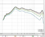
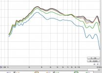
I measured the raw response of two different horns on the same driver. The one horn is the JMLC horn which features the rolled lip on the horn exit. The other horn is identical except the it does not have the rolled lip. See how superior the off-axis response is of the JMLC horn. Off-axis angles are 0,5,10,15,30,46. There is a noticeable difference in sound quality between the two as well. The compression driver is the BMS 4256-08 ring radiator, 5/8” throat, neo magnet.
I measured the raw response of two different horns on the same driver. The one horn is the JMLC horn which features the rolled lip on the horn exit. The other horn is identical except the it does not have the rolled lip. See how superior the off-axis response is of the JMLC horn. Off-axis angles are 0,5,10,15,30,46. There is a noticeable difference in sound quality between the two as well. The compression driver is the BMS 4256-08 ring radiator, 5/8” throat, neo magnet.
Attachments

Joseph Crowe, which is which?
The one on the left looks better to me, the other has an off-axis peak at 8kHz out to 30 degrees, even thought it appear so have better directivity to lower frequencies.
The one on the left looks better to me, the other has an off-axis peak at 8kHz out to 30 degrees, even thought it appear so have better directivity to lower frequencies.
The plot where all the lines look similar is the JMLC horn. If there’s any deviation in relation to the other lines it would be due to edge diffraction off the horn mouth. Edge diffraction is stored energy that shows up in the time domain...namely impulse response, and waterfall plots. This would have direct negative impact on the sound quality...namely dynamic range.
The plot where all the lines look similar is the JMLC horn...
I am surprised at how similar they both are, in different ways, can you be specific - L or R ?
Best wishes
David
It actually looks like the compression driver wasn't centered in the horn's throat as well in the right-hand plots as it is in the left hand plots (or the throat diameter of the horn isn't quite as symmetric). The concentricity requirement of the throat is usually in the 1/10th wavelength regime from experience (about 60-70 thousandths of an inch at 20 kHz, or ~1.7 mm). I've seen that effect before above 9 kHz with 2" compression drivers.
Beyond that, the polar plots down lower in frequency--where the effects of the mouth roll-out will be most prominent--are telling me that continuing the mouth roll-out beyond 90 degrees has no visible effect on the polar traces. Is that what you are referring to?
Chris
Beyond that, the polar plots down lower in frequency--where the effects of the mouth roll-out will be most prominent--are telling me that continuing the mouth roll-out beyond 90 degrees has no visible effect on the polar traces. Is that what you are referring to?
Chris
Last edited:
By the way, I'd recommend a rectangular-mouth horn instead, if you're paying that much attention to horn shape:
"on-axis null" in horn speakers?
Chris
"on-axis null" in horn speakers?
Chris
It actually looks like the compression driver wasn't centered in the horn's throat as well in the right-hand plots as it is in the left hand plots (or the throat diameter of the horn isn't quite as symmetric). The concentricity requirement of the throat is usually in the 1/10th wavelength regime from experience (about 60-70 thousandths of an inch at 20 kHz, or ~1.7 mm). I've seen that effect before above 9 kHz with 2" compression drivers.
Beyond that, the polar plots down lower in frequency--where the effects of the mouth roll-out will be most prominent--are telling me that continuing the mouth roll-out beyond 90 degrees has no visible effect on the polar traces. Is that what you are referring to?
Chris
Driver alignment is within .010” . Also the transition from driver to horn is precisely matched both in exit angle and diameter. This is often overlooked. The horn is designed to match exactly to the BMS driver specifically.
By the way, I'd recommend a rectangular-mouth horn instead, if you're paying that much attention to horn shape:
"on-axis null" in horn speakers?
Chris
That holds true if the horn mouth termination does not eliminate edge diffraction entirely. As a secondary means of dealing with edge diffraction you could go with oval or rectangular which will spread the diffraction around. My kids spread their food around their plate to make it look like they ate more than they did. Pretty clever.
Thanks whgeiger for the papers! Very valuable. Some I know of but still a lot to dig deeper into too.
Joseph, it was surprisingly clear what the complete roundover did to the polar response compared to the truncated.
Chris, Some years ago I did a OS-waveguide with a 1,4" driver, 90 degree, about 40 cm in total diameter and a 1/4 lambda radius mouth roundover. It had a terrible on axis response due to the mouth diffraction as is verified by others too. The dip moves upwards in frequency the further away from the speaker you get due to geometry. This supports the rectangular mouth shape theory, to spread out the diffraction. Also recommended by Danley. However, if diffraction is avoided or smeared inside the waveguide itself, a circular cross section is possible.
Look here on fig 14. No on-axis-dip/peak is seen
Dipole Horn, Dipole Directivity Control Device
I do like the looks of a round waveguide and would like it to perform without devastating diffraction.
- Status
- Not open for further replies.
- Home
- Loudspeakers
- Multi-Way
- Horn mouth roundover, 135 or 180 degrees?