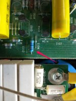
Is there a way to visually identify the preferred older Holco H4 resistor?
Pic below is from a Parasound amp. Any way to tell if this is the newer Holco or if it came this way from Parasound (like John Curl designed) which would make it the preferred one?

Pic below is from a Parasound amp. Any way to tell if this is the newer Holco or if it came this way from Parasound (like John Curl designed) which would make it the preferred one?
Thanks.Use a small magnet 😉 and you get answer....
Magnet didn't attract itself to the resistor ends so it would appear that I have the older Holco H4s?
If the picture is of an HCA-2200II amplifier, they came from the factory with old style UK made Holco H4 resistors.
Thanks.If the picture is of an HCA-2200II amplifier, they came from the factory with old style UK made Holco H4 resistors.
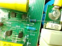
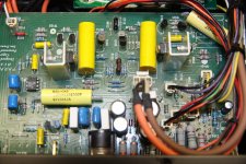
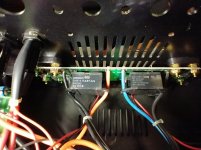
I have two 2200IIs: One has the black colored ones (Holco?) and the other one has bluish colored ones (Resista? - see picture below).
I bought some older H4s off eBay and am thinking I might put them in place of the Resistas but not sure it will be worth the time/effort. I am using that amp as my center channel amp only.
Attachments
I have upgraded many 2200IIs and Holcos are always in R125 (R225) positions. If the amp was purchased used, it's highly likely someone changed them out.
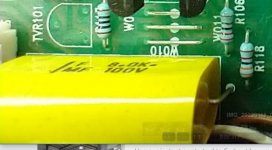
Out of curiosity, these big (in size) yellow caps, what tech are they? MKT or MKP?
I believe these are the same as found in the Klipsch Xover
Many thanks
Claude
I believe these are the same as found in the Klipsch Xover
Many thanks
Claude
Here is a better picture. The darker blue resistor is an "older" Resista that I recently bought off eBay - as you can tell they do not match at all.I have upgraded many 2200IIs and Holcos are always in R125 (R225) positions. If the amp was purchased used, it's highly likely someone changed them out.
When I opened it up, it was pristine inside with not a spec of dust. Almost as if it had been sitting in someone's closet for 20 years. You can see from the picture how clean that board is.
The Parasound literature says they used Holco and Resista but of course that doesn't mean they used a Resista at R125/225.
Attachments
Don't know - here is a better pic.Out of curiosity, these big (in size) yellow caps, what tech are they? MKT or MKP?
I believe these are the same as found in the Klipsch Xover
Many thanks
Claude
Attachments
BTW, I downloaded your modifications sheet and used it as a guide when going through both of my 2200IIs. Thank you for preparing and posting that.I have upgraded many 2200IIs and Holcos are always in R125 (R225) positions. If the amp was purchased used, it's highly likely someone changed them out.
So far, the only mod that I have done is to remove 99% of those while film caps on the power board and all the piggybacked film caps on the input board. This change alone made a huge improvement in detail. Have not found any negatives from doing this.
I really like the way these amps sound.
Attachments
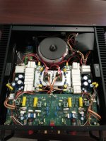
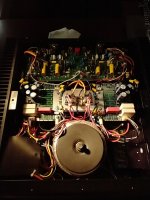
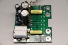
Interesting that you not only removed the piggybacked caps from the input board but it looks like you also removed the film caps underneath them as well.Attached are photos of the driver power supply along with amp input board.
I had some time today and I thought I would go ahead and replace those 2 feedback resistors to the older H4s that I bought.
Well, not sure if I screwed something up but I now cannot get the amp to power up. No standby red light and then no green light. I checked all the fuses and they seem fine. I double checked and triple checked all the wiring connections and everything is as before (I took pics and made notes).
This amp was bought used a few months ago and I have had it in my system running fine however the power switch has been dodgy from day 1 - I would have to toggle it several times to get it to come on. I got tired of doing this and I now power it up from my power center and it has always come on since doing this (power toggle in on position all the time).
Thinking the power switch might have gone bad, I pulled it out and cleaned all the contacts but it still doesn't power up. I am getting about 1.25 volts to the power switch - not sure what should be there. I even bypassed the switch and I still can't get it to power up.
I am wondering if the relay might be bad and it was just coincidence that it happened when it did?
Ideas? Suggestions? Any one know where the relay is located and how I can test it?
Thanks!
I had some time today and I thought I would go ahead and replace those 2 feedback resistors to the older H4s that I bought.
Well, not sure if I screwed something up but I now cannot get the amp to power up. No standby red light and then no green light. I checked all the fuses and they seem fine. I double checked and triple checked all the wiring connections and everything is as before (I took pics and made notes).
This amp was bought used a few months ago and I have had it in my system running fine however the power switch has been dodgy from day 1 - I would have to toggle it several times to get it to come on. I got tired of doing this and I now power it up from my power center and it has always come on since doing this (power toggle in on position all the time).
Thinking the power switch might have gone bad, I pulled it out and cleaned all the contacts but it still doesn't power up. I am getting about 1.25 volts to the power switch - not sure what should be there. I even bypassed the switch and I still can't get it to power up.
I am wondering if the relay might be bad and it was just coincidence that it happened when it did?
Ideas? Suggestions? Any one know where the relay is located and how I can test it?
Thanks!
Make sure all plug-in connectors are in the appropriate sockets. See attached.
Attachments
Thanks for responding.Make sure all plug-in connectors are in the appropriate sockets. See attached.
Yes, I am sure all connections are correct and and they are seated fully to the board. I took pictures and made a sketch before removing the board. I checked very carefully and I just checked them again.
It is likely that I screwed something up with what I did today but it is also eerily similar to the issue I had when I first bought it of not powering up - which I thought was the switch (common problem I think).
It makes no sound now when I turn it on or plug it into power. Not sure how I test a relay or where it is even located. Do you know what voltage I should be seeing at the power switch itself?
Thanks.
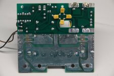
Are these the main relays? How can I test them?
I pulled the input board and rechecked my solders and so forth and also looked the board over to see if something was awry elsewhere and don't see any issues.
This leaves the relays unless the H4 resistors that I bought are defective but not sure that would cause the no power-up issue. I kept the old resistors and I guess I could put them back in if necessary.
Thanks.
Attachments
I should clarify my post above: I know how to test a relay but I don't know how to test a relay that is soldered to a board like these. Can I test it in the same manner? Seems like I won't get accurate readings unless I actually desolder it from the board to test? Can I apply a simulated load?
Also, not sure if these are the main power relays.
Also, not sure if these are the main power relays.
Comparing your sheet to my actual unit, E110 and E210 are reversed: The white/black wires are connected to E110 and the yellow/gray wires are connected to E210. This is they way it was wired when I received it and it was operating fine except for the dodgy power up issue I noted. These wires are all bundled together with zip ties so no way it was reversed by me but someone may have done this in a previous repair.Make sure all plug-in connectors are in the appropriate sockets. See attached.
Would this cause any issues? They look to be just left/right channel thermostat wires for heat overload so reversing them wouldn't cause any detrimental issues - I don't think.
Thanks.
OK, I am a dummy. Turned out to be the main power fuse was blown.
I had convinced myself that the problem was either with the feedback resistor swap that I did and/or the dodgy on-off switch and I failed to realize that the main power fuse is ceramic and does not visually indicate that it is blown. I had no power at the on-off switch which should have given me a big clue but I had convinced myself that the switch itself was bad. Anyway, I used a simple ac tester to follow the power line back to the fuse where I had power in but no power out. Pulled the fuse and checked it and sure enough it was blown. Kicking myself for not realizing this earlier and saving myself some time.
Still not sure why it blew because it was fine before removing it from my rack.
- Home
- Design & Build
- Parts
- Holco H4 Resistor Old vs New - How to identify?