Identical post on ASR ( https://www.audiosciencereview.com/forum/index.php?threads/hodgepodge.61979/ )
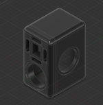
Quick story: Went to my storage unit and found some parts I never used for an old project I canned. A pair of KEF SP1632 drivers and a few dayton 5 1/2" Epique drivers. So I was playing around in CAD to see if I can make something relatively compact. I think I may have stumbled into a cardioid design. Here's what I got:
.png")
.png")
This would be an active design. I found this a little while ago ( https://www.tinyosshop.com/index.php?route=product/product&path=158_193&product_id=1233 ) which should allow me to even out the response between the KEF and the daytons. I would like to put something in the port chambers in order to create small group delay, enough to drag the signal 90 degrees out of phase, but I'm not sure what I could use. DSP would take care of the rest. I still have a lot of little details to work out, but that's the gist of the design. Would love to hear from the community on what I can do to make this work. If it won't work it won't break my heart, but I figure this could be a good learning experience either way🙂
Quick story: Went to my storage unit and found some parts I never used for an old project I canned. A pair of KEF SP1632 drivers and a few dayton 5 1/2" Epique drivers. So I was playing around in CAD to see if I can make something relatively compact. I think I may have stumbled into a cardioid design. Here's what I got:
This would be an active design. I found this a little while ago ( https://www.tinyosshop.com/index.php?route=product/product&path=158_193&product_id=1233 ) which should allow me to even out the response between the KEF and the daytons. I would like to put something in the port chambers in order to create small group delay, enough to drag the signal 90 degrees out of phase, but I'm not sure what I could use. DSP would take care of the rest. I still have a lot of little details to work out, but that's the gist of the design. Would love to hear from the community on what I can do to make this work. If it won't work it won't break my heart, but I figure this could be a good learning experience either way🙂
Yeah I guess it would help if I explained the working theory. Go me 😅
The cardioid part comes from the two drivers I have in the center. Will probably cross it at about 300Hz. From there I would port the two chambers in the same manner to be front firing. The idea was to add material to the port to add group delay just enough to tow the signal 90 degrees out. From there it would just be about adjusting the group delay of the coaxial driver to be in line with the delayed signal coming from the port. In theory, that should be enough to create the cardioid effect (or at least as well as those drivers can I'm not expecting miracles lol).
The cardioid part comes from the two drivers I have in the center. Will probably cross it at about 300Hz. From there I would port the two chambers in the same manner to be front firing. The idea was to add material to the port to add group delay just enough to tow the signal 90 degrees out. From there it would just be about adjusting the group delay of the coaxial driver to be in line with the delayed signal coming from the port. In theory, that should be enough to create the cardioid effect (or at least as well as those drivers can I'm not expecting miracles lol).
Ok so tore down the old idea, did some playing around with it, then completely changed it, and now I have this.
@tktran303 this is what the BMRs are for
Woofer will most likely be the 7" epique driver ( https://www.daytonaudio.com/images/resources/295-104--epique-e180he-44-spec-sheet.pdf ). It has good T/S parameters for the cost and kind of lines up perfectly with what is right above it: a pseudo coaxial array. In its center, will be a set of RAALs I've been meaning to use for some time now. Definitely still some engineering challenges to work out. Still waffling over PRs or sealed. Also need to figure out where to put the DSP. I was thinking just mounting it on the back within its own tiny enclosure. As always constructive critique is always welcome.
Attachments
And the other half of the array is ???a pseudo coaxial array. In its center, will be a set of RAALs
Cross point and slope are ???
Precise driver spacing values are ???
Which all funnels right into: have you simulated the off-axis response? Arrays like you seem to be proposing can be a little dicey if the cross point is high, slope is shallow, spacing is too large, etc. But you haven't given enough info here to give feedback on that aspect.
Maybe those are the midranges? Didn't see them anywhere else in this thread, so we can't know what part numbers are, whether this is what you meant, whether that was a private conversation, etc., so . . . .this is what the BMRs are for
https://cdn.prod.website-files.com/...206066240ef8_BMR85R12-4A Datasheet Rev. A.pdf 4 of theseAnd the other half of the array is ???
LR4 400hz and 2500hzCross point and slope are ???
Pretty much right on each other. Maybe 1/16" at most spacing between each driver. Center to center on the array is 2".Precise driver spacing values are ???
If the literature is to be believed, off axis response should be fairly wide. Not even sure what software I could use to get that data. Is there any that account for bending wave typologies out of the box? Or is that something I would have to fiddle with in something like vituixcad?Which all funnels right into: have you simulated the off-axis response? Arrays like you seem to be proposing can be a little dicey if the cross point is high, slope is shallow, spacing is too large, etc. But you haven't given enough info here to give feedback on that aspect.
I don't have Vituix, but from what I see others saying, it seems like a good choice if you want to fully model the behavior and you can take accurate measurements of each driver or you can find the necessary off-axis data somewhere else.
For basic approximations of issues related to driver spacing and cross points, something like the 3D version of XSim can show you where problems are likely to be. Just use the default perfectly flat data, a textbook crossover, and your driver spacing.
The 2500 Hz cross point helps things, but the Raal tweeters typically have dead space between the ribbon and the edge of the frame, which makes things harder. Unless you do something tricky, it seems like you're inherently going to have extra space between the tweeter's active element and the mids. The co-ax emulating arrays I've messed with have used tweeters with very small flanges, I've back mounted those and front mounted 2.5 inch mids to keep dome/cone spacing very small, and I still always seem to want a lower cross point on the tweeter. 2400 Hz is where I wound up on my last prototype, and it did OK though. I'm also using more shallow crossovers, so I'm making things difficult from that angle.
I'm trying to do everything passive also, so that's different too.
I don't believe it models the directivity though. At least not in my time playing with it. Then again, the interface I have always found a little unintuitive so for all I know I'm missing something.I don't have Vituix, but from what I see others saying, it seems like a good choice if you want to fully model the behavior and you can take accurate measurements of each driver or you can find the necessary off-axis data somewhere else.
Oh haven't heard of this one! Will definitely check out 🙂For basic approximations of issues related to driver spacing and cross points, something like the 3D version of XSim can show you where problems are likely to be. Just use the default perfectly flat data, a textbook crossover, and your driver spacing.
I figured the BMR would help fill in the gaps with that so to speak. Since they have a much higher directivity index than regular speakers, beaming wouldn't start until a bit higher. Then again, I could always try to cross lower, but when I messaged Alex he said 2500 is usually a good spot to start.The 2500 Hz cross point helps things, but the Raal tweeters typically have dead space between the ribbon and the edge of the frame, which makes things harder. Unless you do something tricky, it seems like you're inherently going to have extra space between the tweeter's active element and the mids. The co-ax emulating arrays I've messed with have used tweeters with very small flanges, I've back mounted those and front mounted 2.5 inch mids to keep dome/cone spacing very small, and I still always seem to want a lower cross point on the tweeter. 2400 Hz is where I wound up on my last prototype, and it did OK though. I'm also using more shallow crossovers, so I'm making things difficult from that angle.
As far as I can tell, Vituixcad is actually very good for passive crossovers, as it helps model them within a given enclosure. If nothing else I would urge you to take a peek at it and see if it can do anything for you. My only gripe, like I said earlier, is that the interface can be a little confusing. At worst it's a good place to get some ideas on drivers. In the enclosure tool they have a list of drivers from different manufacturers. Some I've never even heard of.I'm trying to do everything passive also, so that's different too.
Edit: I forgot to mention, the RAAL in question is the 70-20, which also has a little extra flexibility.
I'm not sure the BMR is going to help much with the spacing issue, but I haven't messed with them. The root of the problem is the varying path lengths between the mid- and high-frequency sources when you start going off axis. In a normal speaker configuration, this shows up when you go vertically off axis, so you typically see much worse behavior in that direction than in the horizontal. In a co-ax emulating array, you have the problem all around, instead of just vertically.
Philharmonic's ribbon seems longer, and the spacing to the BMR mid is maybe larger than you're proposing, but it's displaying vertical off-axis issues. Maybe not as severe as you'd have with similarly sized normal cone mid, but hard to say for sure.
https://www.erinsaudiocorner.com/loudspeakers/philharmonic_bmr/
And again, I haven't done exactly what you're proposing, so maybe it's fine. I normally mock up things like this as quickly and cheaply as I can to run basic off-axis tests.
Last edited:
Vituix doesn't model cone modes/breakup. It's probably too specialised an effect to expect any regular speaker design simulator to do.I don't believe it models the directivity though.
If you can measure your own polars, vituix will let you move them around within a virtual space and calculate their interactions accordingly.. However it doesn't keep up with the baffle configuration that would go along with these positional changes, instead it simply moves the associated polars to a new source position. This is perfect for ordinary things like putting multiple mids on the front of a box.
I think @mattstat has the right idea. Maybe I could fashion a small test rig to get actual data instead of relying on simulation. That way I'll know the exact polar pattern it would make instead of just trying to guess. Nobody says I can't just mount them real quick in a slab of mdf and test it with something like REW to get a measurement.Vituix doesn't model cone modes/breakup. It's probably too specialised an effect to expect any regular speaker design simulator to do.
If you can measure your own polars, vituix will let you move them around within a virtual space and calculate their interactions accordingly.. However it doesn't keep up with the baffle configuration that would go along with these positional changes, instead it simply moves the associated polars to a new source position. This is perfect for ordinary things like putting multiple mids on the front of a box.

A thought occurs to me. If I put the T/S parameters into vituixcad, and use the polar plots from the spec sheet, would that give me enough of an approximation to give me an idea of actual results? The measurements are technically in far more optimistic conditions than I could create. My only concern there is if the spec sheets were doctored at all.
I didn't say it explicitly, but that was one of the things I was implying when I said, "or you can find the necessary off-axis data somewhere else."
Most spec sheets use smoothed data, but the amount of smoothing varies. Given your cross points and the kind of problem we're discussing, smoothing probably isn't a significant problem.
Most spec sheets use smoothed data, but the amount of smoothing varies. Given your cross points and the kind of problem we're discussing, smoothing probably isn't a significant problem.
Apologies. I thought you were saying "literal" data from a second or third party. The drivers are very new so there really isn't a whole lot of data out there on them.I didn't say it explicitly, but that was one of the things I was implying when I said, "or you can find the necessary off-axis data somewhere else."
Cool! Then I guess it's time to torture myself and go figure out vituixcad againMost spec sheets use smoothed data, but the amount of smoothing varies. Given your cross points and the kind of problem we're discussing, smoothing probably isn't a significant problem.

No. T/S parameters are not of much use in acoustic modelling of this nature, although they can't hurt.If I put the T/S parameters into vituixcad, and use the polar plots from the spec sheet, would that give me enough of an approximation to give me an idea of actual results?
What you need is modelling of the outside of the box. Normally, vituixcad can take factory polars and apply their effect to a simulated baffle on a box, which is good enough for testing a concept with a simple configuration..
If you want to modify the driver directivity with an intermediate stage, such as mounting it on a duct where the directivity has greater dependence on the interface between the other end of the duct and it's baffling, then you might be out of luck (unless you can think outside the box and somehow trick vituixcad into applying a similar effect.)
I was actually thinking about maybe just taking multiple measurements of the same driver, one for horizontal orientation, and then one for vertical. Last one would be for the 70-20. The issue there is accounting for the odd shape of it.If you want to modify the driver directivity with an intermediate stage, such as mounting it on a duct where the directivity has greater dependence on the interface between the other end of the duct and it's baffling, then you might be out of luck (unless you can think outside the box and somehow trick vituixcad into applying a similar effect.)
But rather than doing backflips to try and fit a square peg in a round hole, maybe we should just ask @kimmosto and see if he has any ideas.
- Home
- Loudspeakers
- Multi-Way
- Hodgepodge