Good evening everyone,
Through work I have just received a few items of vintage audio. And I'm after some more info on the Hitachi HA-250 amplifier as oogle is fetching nothing up.
I am looking to maybe modify it, but it sounds sweet how it is, after I cleaned the pots, was surprised to see nipon chemi/com caps and an alps volume pot. If anyone could shed any light on this amp.
So far the only things I can think of doing to it, is rewire with better quality cables and better cooling (runs like a radiator).
On a side line;
Also got a marantz tape deck from the same era which looks in mint condition and has the VU meters on it, was wondering if I could integrate them with the amp, or if its best selling it to a collector and someone who will love it.
Will upload some pics tomorrow, and the last thing I'm not sure what to do with, is a valve amplifier that seems to date back to ww2 era. It needs work in restoring it, but the transformers are huge as are the valves them selves, and they seem to have a wire and cap going to the top of them, something I've not seen before. Any info on what to do with this would help. Or if anyone is interested in it
Thanks in advance
quick net search and looks like I have found the amp Vintage Amps Bulletin Board • View topic - Vortexion 50w Custom Boogie but the one I have is in original condition. Not sure what to do with it. Anyway thats a side line. More interested in the Hitachi
Hi, just after some quick help with this amp.
I've rigged up a crude circuit so I can use some VU meters for some eye candy. And they work fine.
However they don't "kick" in early enough so I'm guessing I would need to lower the input resistor. And they seem to peak before I have it at my reference volume. So I was thinking or inserting a trim pot before the VU meter.
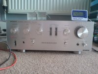
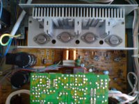
Below is how I have wired it up, and them in "situ" for testing. Wonderful amp. Once I finish tweaking it I intend to design two cases and have it as a pre/power amp combo.
I have upgraded the heatsinks (hence the thermometer, was like a radiator before) so far and just added the VU meters. Not sure what to do next on it still deciding.
Any help with regards to the values would be great
Excuse the crude drawing, but would lowering R1 to 3300ohms allow them to kick in earlier, and would putting a variable resistor after C1 allow me to trim the meter to stop it peaking.
Next, its working out where to tap of the supply for the meter lamps.
I've rigged up a crude circuit so I can use some VU meters for some eye candy. And they work fine.
However they don't "kick" in early enough so I'm guessing I would need to lower the input resistor. And they seem to peak before I have it at my reference volume. So I was thinking or inserting a trim pot before the VU meter.
Below is how I have wired it up, and them in "situ" for testing. Wonderful amp. Once I finish tweaking it I intend to design two cases and have it as a pre/power amp combo.
I have upgraded the heatsinks (hence the thermometer, was like a radiator before) so far and just added the VU meters. Not sure what to do next on it still deciding.
Any help with regards to the values would be great
Excuse the crude drawing, but would lowering R1 to 3300ohms allow them to kick in earlier, and would putting a variable resistor after C1 allow me to trim the meter to stop it peaking.
Next, its working out where to tap of the supply for the meter lamps.
Attachments
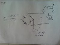
Germanium diodes are must for any passive VU/power meter because of their much reduced volt drop. With a silicon bridge you need around 1volt before any conduction takes place. Half wave is much better. The 140uF seems a bit large too.
With a passive circuit you are really struggling because of the meter ballistics (they need a finite time to respond) and transients in music are far shorter usually.
The real answer is an active driver using an opamp with diodes in the feedback loop to eliminate the volt drop. Maybe worth looking at some old cassette deck manuals for a simple circuit.
Thanks Mooly, always good advice.
Yeah I was thinking about the voltage drop on the diodes, but they were all I had lying around.
With regards to the 140uF cap, I tried experimenting with a few, at first I tried a 47uF but the needle was dancing around too much and then upped them until I found one with a nice slew rate on the needle.
Funny you should mention the cassette, I actually pulled the needles from a Marantz 5050m tape deck but didn't look too much in to that circuit.
An active driver, come to think of it, I have a Technics power amp with the VU meters (mini power amp), it's dead and don't think I'm going to use it, so will have a look at that circuit and see if I can grab the driver stage from that amp.
Only went down the passive route as I didn't want/know where I would power an active circuit from that amp. Will have a look at the Marantz and Technics circuits tonight and see if I can figure something out. Can't wait to finish messing around with the amp and start designing the new case.
Been trying to get hold of a service manual for this amp, but there is next to no info on the net for it. Surprises me as it's really nice sounding and uses good quality components.
Sorry Edit;
Being abit stupid today, I have geranium diodes on already as I have quite alot of them from old college projects, maybe I should look at changing R1 to 3300 ohms.
Being abit stupid today, I have geranium diodes on already as I have quite alot of them from old college projects, maybe I should look at changing R1 to 3300 ohms.
Getting a low current supply for a meter driver from the amp PSU is dead easy. Nothing more than a resistor and zener to suit fed from the main reservoir cap. For a meter driver we are talking low current, say a 12 volt supply at a couple of milliamps.
It's got to be active really if you want them to move at low levels. Definitely look at some cassette deck manuals. Try looking up the Sony TC136SD and Sony TCK5 of the late 1970's early 80's. I think they were just a one transistor driver.
It's got to be active really if you want them to move at low levels. Definitely look at some cassette deck manuals. Try looking up the Sony TC136SD and Sony TCK5 of the late 1970's early 80's. I think they were just a one transistor driver.
Will have a look at the driver stage on the marantz tape deck tonight Mooly, and see if I can get something rigged up, if not I have some opamps laying around. Will let you know tomorrow and get something rigged/designed up.
These old AB amps do not run hot. There is probably a fault somewhere. Too high idle current seems likely.
Also, making two cases with the pre and power amp parts seems unneccessary. It looks rather nice, and it would be a shame to "waste" it like that. The sound would not change, either. Why not make a brand new pre/power amp instead?
Also, making two cases with the pre and power amp parts seems unneccessary. It looks rather nice, and it would be a shame to "waste" it like that. The sound would not change, either. Why not make a brand new pre/power amp instead?
Hi Coconuts,
I do run the amp quite loud and a few times I have had the thermal protection kick in. It doesn't get massively hot.
But the old "heatsink" was just a sheet of steel. Come to mention it, I have been monitoring the temperature in idle and its still in the mid 40s like it has a load through it.
I don't have a service manual for it, so I would be going in blind in doing meter readings. But will have a look.
Must say I do like the look of it too, it was just an idea I was toying with, having thought about it, I think I will keep the front panel as is, and just redo the chassis and inputs.
Wouldn't mind doing a separate pre/power amp combo based on the Musical Fidelity XA-50s but that will be for another thread.
Hi Mooly, had a look around at the donor cassette player the VU meters came out of and that uses a one transistor driver stage like you mentioned, will trace the components back and then draw up circuit diagram and post it to make sure I've not got some other components mixed up lol.
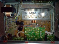
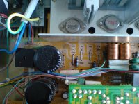
Hi as promised some pictures of the circuits sorry for the delay been busy with work.
Excuse the dustyness not had chance to clean it up yet as still in the experimenting stage.
Wanting to check the DC bias and maybe readjust if it needs it. I can't find a service manual anywhere. So was hoping someone with more experience can point me in the right direction. Any help would be appreciated.
Attachments
Without a manual I wouldn't like to hazard a guess at the "recommended" bias current.
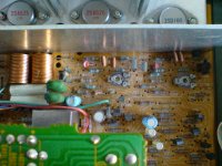
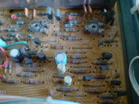
I was looking for (and couldn't see) some low value resistors in the 0.1 to 0.47 ohm region that would be in the emitter (or collector) leads of the output transistors. They could be used to determine the bias by measuring the volt drop across them.
The bias value could be critical as there only looks to be a thermistor (the red two legged components) for temperature compensation rather than a vbe multiplier (transistor) coupled to the heatsink. Get it wrong and the amp could go into thermal runaway.
There must be an easy way to set it but I can't see from the pictures. Look for test points across a low value resistor or a link that can be removed and an ammeter inserted to measure the current for each channel It could be in either the emitter or collector leads of the outputs.
The Hitachis of that vintage were CFP output stages, running with around 100 mA bias per output pair. Bias is adjustable but as someone who experiments too much, I found the stability is not good away from that level. Anyone using consumer CFP amps with low or "correct" 13 mA bias would tell you that they are a bit harsh at low levels so I imagine this was Hitachi's solution. Quite a few people have commented that these sound(ed) quite good but ran hot and need clear airways to survive thrashing at at high power.
I think they're actually good, lasting products, if I have the details correct about this particular model.
I think they're actually good, lasting products, if I have the details correct about this particular model.
Hi Ian thanks for that input.
I don't have the experience to just jump in and start messing around with the bias blind. Unless I get hold of a service manual, I'm just going to enjoy the sound until something breaks on it.
Sound quality I must say is very good surprising actually. Yeah it does run hot, hence the extra heat sinks on it, otherwise thermal protection kicks in when at high power. I have no information on the amp like tech specs or anything. But would recommend it.
I have just been servicing one of these. Always worth checking the four 120 ohm resistors that run along near the front edge of the heatsink, as well as the four 47 ohm resistors underneath the board in similar area (inside insulator tubes). In this one all had gone rather high, or open circuit, and were causing distortion. Having replaced them all in this one, I would always do the same in another HA-250, just to make sure 🙂
Bias current...
Had a look over the HA-250 circuit - there are two emitter resistors, R720 (L) and R720 (R), with a value of 0.22 ohms. They're down closer to the power supply section, encased in insulating sleeves.
To set bias at 100mA, measure voltage across each resistor in turn, and adjust the appropriate pot (VR701 L or R) accordingly. There is a test point to do this, with the other lead of the meter going to the negative supply connection (but not earth). If you're not sure, just measure across the resistor. Mine was running a little high, resetting it has noticeably cooled it down at idle.
The 100mA value is based on Ian Finch's suggestion earlier in this thread. Whether or not it's the correct value, I think it would be fair to say that you shouldn't go over it, so if yours measures higher, you can step it back.
*** Note that the RH emitter resistor is actually on the left and vice versa, so don't get mixed up which channel you are measuring! ***
I should clarify re bias adjustment - to set current to 100mA, adjust for 22mV across the emitter resistor.
I have one to fix as well so if a circuit is avaiable please email it to me ian.griffin@griffin-elevators.co.uk.
Thanking You 😉
Thanking You 😉
used the scheme from HA-330I have one to fix as well so if a circuit is avaiable please email it to me ian.griffin@griffin-elevators.co.uk.
Thanking You 😉
- Status
- Not open for further replies.
- Home
- Amplifiers
- Solid State
- Hitachi stereo amplifier HA-250