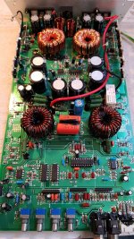
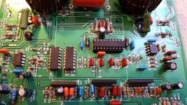
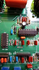
Power supply voltage is 10v
Brand new HIP4080A
Pin 1: 18.88v
Pin 2: 11.95v
Pin 3: 0.013v
Pin 4: 0.004v
Pin 5: 0.003v
Pin 6: 5.26v
Pin 7: glitching voltage between 10.4v and 11.05v
Pin 8: 5.14v
Pin 9: 5.14v
Pin 10: 19.08v
Pin 11: 19.08v
Pin 12: 6.23v
Pin 13: a bit variable with an average of 11.6v
Pin 14: 0v
Pin 15: 12v
Pin 16: 12v
Pin 17: 0v
Pin 18: 0v
Pin 19: 6.25v
Pin 20: 19.06v
Attachments
Last edited:
This is close to what you have:
http://www.bcae1.com/temp/Fusion-FP9001D caramp - 4080 like stealth.pdf
Confirm that R38 is soldered on both ends.
What power supply voltage is 10v?
http://www.bcae1.com/temp/Fusion-FP9001D caramp - 4080 like stealth.pdf
Confirm that R38 is soldered on both ends.
What power supply voltage is 10v?
10v is the input voltage going into the amplifier
R38 is correctly soldered on both ends.
I noticed, please watch R34, this resistor has been blown out (connected to Pin 4 of the HIP4080, which is VSS) I tried the resistors 10k, 5.1k, 1k, 150ohm. No results unfortunately
There is absolutely nothing happening with this HIP4080. Not a single PWM wave or sawtooth wave is coming in or out.
Last edited:
To have less heat caused by a higher wattage in heat losses in case of a defect. A tip I saw on Barevids video's.
My power supply can't limit the current draw on a steady voltage. It drops voltage when the adjusted max current draw has been reached.
I have tried 14.4v several times on this amplifier before. Didn't have any effect on the HIP4080.
My power supply can't limit the current draw on a steady voltage. It drops voltage when the adjusted max current draw has been reached.
I have tried 14.4v several times on this amplifier before. Didn't have any effect on the HIP4080.
Some amps won't function normally on 10v.
A current limiting resistor (2 ohm 100w) on the B+ line was the best option for me. I didn't like the operation of the current limiters on either of my supplies.
Connecting a 12v buzzer across it to give an audible indication of current draw helped.
What runs cooler on 10v than on 14.4v?
Do you have a triangle waveform on pin 6?
Sounds like a real good one. Luckely I have a spare 2ohm 100w resistor.
I will try this 🙂
For example, when I have a problem in the output section, and the amplifier draws 2amps at 14.4v, and 1.4amps at 10-11v.
At both voltages the power supply fets heat up.
At 10v I'm able to keep the power supply fets at a steady safe temperature with a 12v cooling fan, so I can throubleshoot.
At 14.4v the power supply fets heat up to a critical temperature, even with cooling fan.
Pin 6 of the HIP4080 has no triangle wave form.
It seems to be connected through R42 to pin6 of the HEF4069
Let's compromise and use 12v. I'd suggest using about 13.5v if using the 2 ohm current limiting resistor.
Are you sure that pin 6 isn't connected to pin 2 of the 4069 via a 220 ohm resistor, as shown in the diagram?
Are you sure that pin 6 isn't connected to pin 2 of the 4069 via a 220 ohm resistor, as shown in the diagram?
Check, 12v power supply voltage.
Yes, pin 2 of the HEF4069 seems not to make any connection with pin 6 of the HIP4080.
Pin 6 HIP4080 is connected to R42 (lets say +), then going from R42- to C27 and Pin6 HEF4069
Pin 6 HEF4069 is the OUTPUT pin
Pin 5 HEF4069 is the INPUT pin
Pin 5 is connected to the burned/missing resistor R34
I measured some things:
- C27 is CS1 (your service manual)
- R42 is RS1
Attachments
Last edited:
So, is the circuit the same as in the diagram but with a different connection to the pins on the 4069?
Pin 6 HIP4080 has now a present triangle wave (no output pwm).
I noticed in the datasheet and the connections that R43 should not be present. Removing R43 created a triangle wave.
I noticed in the datasheet and the connections that R43 should not be present. Removing R43 created a triangle wave.
What datasheet are you referring to? What page number or diagram?
With pin 6 having a triangle waveform, do you now have audio? Or at least rail-rail oscillation on the output FETs?
With pin 6 having a triangle waveform, do you now have audio? Or at least rail-rail oscillation on the output FETs?
I was referring to page 16 of the FP-9001d datasheet.
It seems like the datasheet is identical to this amplifier, just a different pin configuration from the HEF4069.
There is a triangle wave present on Pin6 HIP4080
There is no rail-rail oscillation going to the output fets.
It seems like the datasheet is identical to this amplifier, just a different pin configuration from the HEF4069.
There is a triangle wave present on Pin6 HIP4080
There is no rail-rail oscillation going to the output fets.
What's the DC voltage on pin 6 of the 4080?
It should be approximately 1/2 of the voltage on pin 15.
What's the DC voltage on pin 7 of the 4080?
It should be approximately 1/2 of the voltage on pin 15.
What's the DC voltage on pin 7 of the 4080?
Post the DC voltage on all terminals of the 5532. Copy and paste the following list and fill in the blanks.
Pin 1:
Pin 2:
Pin 3:
Pin 4:
Pin 5:
Pin 6:
Pin 7:
Pin 8:
Pin 1:
Pin 2:
Pin 3:
Pin 4:
Pin 5:
Pin 6:
Pin 7:
Pin 8:
Pin 1: 11.25v
Pin 2: 6.28v
Pin 3: 6.28v
Pin 4: 0.01v GND
Pin 5: 6.28v
Pin 6: 6.28v
Pin 7: 6.28v
Pin 8: 11.95v VCC
Pin 2: 6.28v
Pin 3: 6.28v
Pin 4: 0.01v GND
Pin 5: 6.28v
Pin 6: 6.28v
Pin 7: 6.28v
Pin 8: 11.95v VCC
- Home
- General Interest
- Car Audio
- HIP4080A not creating pwm


