i want to try my hand at making a chip amp and i have a lm3876 and also a surplus tranny i ripped out of an old amp--the tranny is center tapped and 33vac on each side.. after rectify and smoothing this will be around 40v--is this too much for this chip?? data sheet shows 84v max but just wondering if anyone has used this high of a voltage
-chris
-chris
Well, I can't speak from experience, but I think you won't have problems if you (1) oversize the heatsink from what the datasheet says, and (2) only run well-behaved 8R speakers.
For the heat sink, I would avoid isolating them, and instead come up with a chassis design that would allow them to sit at V- for better heat xfer, making them internal and isolated from the chassis.
For the heat sink, I would avoid isolating them, and instead come up with a chassis design that would allow them to sit at V- for better heat xfer, making them internal and isolated from the chassis.
Personally I wouldn´t exceed the maximum ratings.
If I understand you correctly you´ve got 66VAC centertapped so
you´d get around +-46VDC which is well above the +-42V maximum rating National Semiconductor recommends.
You can of course give it a try but be prepared it won´t sound good (or even blow???).
You might wanna have a look here for probable consequences of too high a voltage transformer : http://www.diyaudio.com/forums/showthread.php?s=&threadid=13593
Regards
Jens
zx3chris said:i want to try my hand at making a chip amp and i have a lm3876 and also a surplus tranny i ripped out of an old amp--the tranny is center tapped and 33vac on each side.. after rectify and smoothing this will be around 40v--is this too much for this chip?? data sheet shows 84v max but just wondering if anyone has used this high of a voltage
-chris
Much to high voltage. If you absolutely need to use that transformer I would recommend regulating the voltage to something more useful which is anything some distance away from 42 V.
And yes somebody has already used that high voltage and he publicly apologize for it.
I was thinking that a possible solution is to "slave" the +/- rails. That is, you use a set of transistors to drive the lm3876 power rails with a voltage that is proportional to the output audio signal. It's something similar to what older amplifiers did to solve the SOA problem of high rail voltages. I think this was called a totem-pole output stage, but in this case, the whole amplifier is being driven this way, even the input stage.
Maybe somebody could comment on if the input stage of a lm3876 would like a dynamic power supply input?
I am not sure if such a trick would work with a lm3876.
Maybe somebody could comment on if the input stage of a lm3876 would like a dynamic power supply input?
I am not sure if such a trick would work with a lm3876.
Has anybody read the review of Bob Carver´s Sunfire amplifier?
It keeps the supply voltage 6V above what is needed for the momentary output power to minimise dissipation.
The 20 output transistors are just mounted to the case bottom.
Delivers 600W into 8Ohms with an "endless" current capacity.
Should work below 0.5Ohms.
And just took 25 years of development time.
Jens - doesn´t need 600W but likes the idea
The 33-33 would be just ducky for the R. Elliot 3a amp. Keep it around.
the 3876 is set for 30-30dc which is around 22.5,22.5vac.
There is not much point in exceeding the ratings as the per-chip dissipation is really on the low side with these beasties! althoug the 3886
sez it is ok for 38-38 dc it will reach its thermal limits easily, and is for 8-ohms only.
the 3876 is set for 30-30dc which is around 22.5,22.5vac.
There is not much point in exceeding the ratings as the per-chip dissipation is really on the low side with these beasties! althoug the 3886
sez it is ok for 38-38 dc it will reach its thermal limits easily, and is for 8-ohms only.
the speakers i plan on driving are a set of peerless speakers i made a whle back and unfortunately they are 4ohm.. they do sound excellent, and the reason for 4 ohm is that they were going to go in my car, but i had trouble with the clearance of the woofer and my door/window--so i made them for my house. right now i am powering them off an old car head unit and a computer AT supply--they are only getting ~15 watts but sound nice--however they can go up to 150watts so id like to push them if i could--so i wanted to make an amp based on the 3876 (since i have it already) and drive 4ohm safely. i will keep on the lookout for some 22-22 transformers. thanks for the information
-chris
-chris
zx3chris,
Another thing you can try is straying from the IGC philosophy, and instead building a half-wave rectifying stage for that xformer with big caps to smooth the DC. That'll give something like +/- 22 VDC, so you'll be struggling with lower power rather than thermal protection 🙂
Another thing you can try is straying from the IGC philosophy, and instead building a half-wave rectifying stage for that xformer with big caps to smooth the DC. That'll give something like +/- 22 VDC, so you'll be struggling with lower power rather than thermal protection 🙂
if i make half wave rectifying instead of full wave, how can i estimate the dc out?? would [ (VAC/.7) - .7 ] /2 be good?? in that case it would be +/-23VDC... if this works, in most gainclose i always seen people using simply 1000uf caps, what value caps should i use??
-chris
-chris
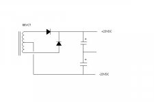
something like this perhaps??
i am using multisim to simulate and for some reason when i put in an electrolytic capacitor the simulation did not come up right so i had to create these 1000uF non electrolytics...
the scope is showing vac in (top) and vdc out (bottom), the meter is showing vdc rms.. i guess just a high current diode would be fine?
-chris
An externally hosted image should be here but it was not working when we last tested it.
i am using multisim to simulate and for some reason when i put in an electrolytic capacitor the simulation did not come up right so i had to create these 1000uF non electrolytics...
the scope is showing vac in (top) and vdc out (bottom), the meter is showing vdc rms.. i guess just a high current diode would be fine?
-chris
Unlikely this will work. You can't create a solid ground reference from two capacitors.leadbelly said:I think this is how it'd work:
Can someone else comment?
with no load the dc out will be your usual ac*root2
if the caps are big enough to charge then supply the current during the missing alternate cycles under load it will stay up close to above but current thru diodes will be at least double the average draw
when the caps run out before the next cycle starts the voltage "ripples" so the average measured by a meter
is lower, depends on the draw
ps paulb is correct - correct reference: the one way symmetric diagram *using only half (ct-one side) of your winding* on the link joensd
Hi Chris, I agree with others. 33VAC would be too high after rectification and filter. I built mine with +/- 38 volts and it drive My Apogees Stage without problem. It sound gorgeous on my stages as a matter of fact, though I think you have to mate it with a smooth and laid back, usually Tube and/or non-feedback solid state preamps. It may turn hard with the usual high feedback preamp. You can certainly use just one side of the tap, then use it as a single supply design as in the National Application note. Hope it helps
leadbelly, the transformer is already center tapped so i would use the circuit i posted on each tap to make +/- voltage..
i will check the data sheet more, thank for the info
-chris
i will check the data sheet more, thank for the info
-chris
zx3chris,
No, you can't use all 3 taps and have it work. Reread davesaudio's post.
But I would still like an answer to the splitting of a winding question, just to answer it for my own possible use. There have been posts on it, I remember one by Peter Daniel, but I can't find them now.
No, you can't use all 3 taps and have it work. Reread davesaudio's post.
But I would still like an answer to the splitting of a winding question, just to answer it for my own possible use. There have been posts on it, I remember one by Peter Daniel, but I can't find them now.
i reread davesaudio's post but i still dont understand wh wouldnt the below circuit work?? using all 3 taps for +/-. i simulated a center tap by tying the two vac sources together
negative voltage has diode in other direction
-chris
negative voltage has diode in other direction
-chris
An externally hosted image should be here but it was not working when we last tested it.
- Status
- Not open for further replies.
- Home
- Amplifiers
- Chip Amps
- high voltage lm3876